Part Names and Functions
40
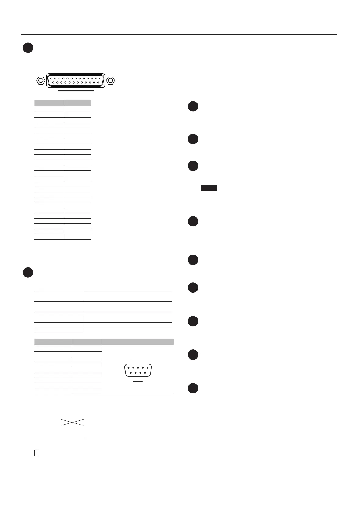
4 GP I/O Connector
This is a D-sub 25-pin connector (4 in/12 out) for sending and
receiving control signals to and from an external device.
113
1425
Connector No. Type
1 GPO 1
2 GPO 3
3 GPO 5
4 GPO 7
5 GND
6 GND
7 GND
8 GND
9 +5V
10 GPI 2
11 GPI 4
12 GPO 10
13 GPO 12
14 GPO 2
15 GPO 4
16 GPO 6
17 GPO 8
18 GND
19 GND
20 GND
21 +5V
22 GPI 1
23 GPI 3
24 GPO 9
25 GPO 11
Input pin [Voltage detection range: 0-5V , Max +5V]
Output pin [Open collector , Vmax=12V , Imax/pin=75 mA]
DC output [DC+5V / 1000mA]
5 RS-232C Connector
You can use this RS-232C connector to control the M-5000 remotely
from an external device.
Transmission method
Start-stop synchronization (asynchronous mode),
full-duplex
Communication speed
(baud rate)
4800, 9600, 14400, 31250, 38400, 57600, 115200
bps
Parity None
Data length 8 bit
Stop-bit length 1 bit
Code set ASCII
Connector No. Signal name Pin connections
1 NC
1 5
6 9
2 RXD
3 TXD
4 DTR
5 GND
6 DSR
7 RTS
8 CTS
9 NC
Computer
1 :
2 : RXD
3 : TXD
4 :
5 : GND
6 :
7 :
8 :
9 :
M-5000
1 : NC
2 : RXD
3 : TXD
4 : NC
5 : GND
6 : NC
7 : RTS
8 : CTS
9 : NC
* Pins 7 and 8 are connected inside the M-5000.
* For the M-5000 to function, the three pins RXD, TXD, and GND
must be connected as shown in the gure.
* In addition to the owner’s manual, RS-232C Reference Manual
(PDF) is available as a reference material that covers RS-232C
port control.
Download the PDF le from the Roland website.
* RS-232C Reference Manual (PDF) contains the following
information.
5 Information on setup
5 Overviews, detailed explanations, and lists of commands
6 MIDI Connectors
These are connectors for attaching MIDI devices. An IN connector
(for reception) and an OUT/THRU connector (for transmission and
“thru”) are provided.
7 AES/EBU OUT 1/2, AES/EBU OUT 3/4 Jacks
These jacks output digital audio signals in AES/EBU format
(IEC60958-compliant).
8 AES/EBU IN 1/2, AES/EBU IN 3/4 Jacks
These jacks input digital audio signals in AES/EBU format (IEC60958-
compliant).
NOTE
The AES/EBU IN 1/2 and AES/EBU IN 3/4 jacks are not equipped
with a sampling-rate converter. Input digital audio signals
synchronized to the M-5000’s word clock.
9 DOCK CABLE Connector
This is for connecting an iPad using the dock cable included with
the M-5000. This lets you operate the unit remotely and perform
audio input and output on 2 channels using the iPad.
Charging starts automatically when an iPad is connected.
10 LAN Port
This is an RJ45 connector for connecting a computer or Wi-Fi router.
It lets you operate the M-5000 remotely using a computer or iPad.
11 LAN-cable Hook
This secures the LAN cable connected to the LAN port. This can help
prevent inadvertent detachment of the LAN cable.
0“Using the LAN-cable Hook” (p. 24)
12 USB WLAN ADAPTER Connector
This is a USB port for connecting a wireless USB adapter (WNA1100-
RL, sold separately).
It lets you connect an iPad, computer, or Wi-Fi router.
13 USB COMPUTER Connector
This is a USB port for connecting a computer.
It lets you operate the M-5000 remotely and perform audio input
and output on 16 channels.
14 REAC Ports (A B, SPLIT/BACKUP)
These are RJ45 connectors for attaching input/output units (such
as the S-2416, S-1608, S-0816, and S-4000S) using Cat 5e Ethernet
cables.
The unit has two series of REAC ports (A and B). The SPLIT/BACKUP
port can split or duplicate the REAC A or B connection.
The REAC SPLIT/BACKUP port is compatible with REAC EMBEDDED
POWER, and can supply power to devices compatible with REAC
EMBEDDED POWER.
When a REAC device is connected, the system automatically detects
whether the device is compatible with REAC EMBEDDED POWER
and supplies power if compatible.
Power is not supplied if the device is not compatible with REAC
EMBEDDED POWER.
 Loading...