3: Functions and features Model 2461 Interactive SourceMeter® Instrument
3-86 2461-901-01 A/November 2015
Digital I/O
The Model 2461 digital I/O port provides six independently configurable digital input/output lines.
You can use these lines for digital control by writing a bit pattern to the digital I/O lines. Digital control
is used for applications such as providing binning codes to a component handler. Digital control uses
the state of the line to determine the action to take.
You can also use these lines for triggering by using the transition of the line state to initiate an action.
The instrument can generate output trigger pulses and detect input trigger pulses. Triggering is used
for applications such as synchronizing the operations of a source-measure instrument with the
operations of other instruments.
You cannot configure or directly control the digital I/O lines from the front panel. To configure and
control any of the six digital input/output lines, you need to send commands to the Model 2461 over a
remote interface. You can use either the SCPI or TSP command set. See Remote communications
interfaces for information about setting up a remote interface and choosing a command set.
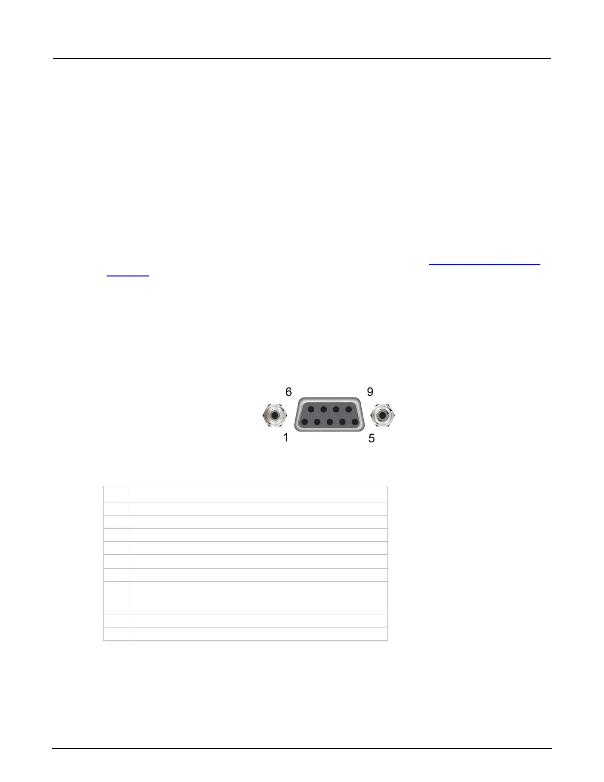
Digital I/O connector and pinouts
The digital I/O port uses a standard female DB-9 connector, which is located on the rear panel of the
Model 2461. You can connect to the Model 2461 digital I/O using a standard male DB-9 connector.
The port provides a connection point to each of the six digital I/O lines and other connections as
shown in the following table.
Figure 130: Model 2461 digital I/O port
Model 2461 digital I/O port pinouts
Pin Description
5
V
ext
line (relay flyback diode protection; maximum 33 V)
+5 V line. Use this pin to drive external logic circuitry. Maximum
current output is 500 mA. This line is protected by a self-
resetting fuse (one-hour recovery time).

 Loading...