April 2017
4-69
Xerox® VersaLink® B7025/B7030/B7035 Multifunction Printer
REP 12.10, REP 12.11
Repairs and Adjustments
Launch Issue
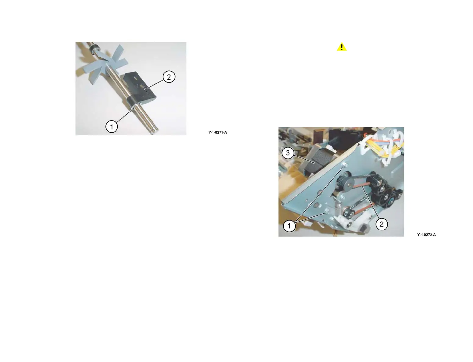
8. Remove the support bearing from the main paddle shaft assembly, Figure 6:
a. Remove the E-clip (1).
b. Remove the support bearing (2).
Figure 6 Support bearing removal
Replacement
The replacement is the reverse of the removal procedure.
REP 12.11 Lower Chute Assembly
Parts List on PL 12.12
Removal
WARNING
Switch off the electricity to the machine. Refer to GP 10. Disconnect the power cord
from the customer supply while performing tasks that do not need electricity. Electricity
can cause death or injury. Moving parts can cause injury.
1. Remove the stapler assembly, refer to REP 12.4.
2. Turn over the integrated office finisher.
3. Remove the transport motor, Figure 1:
a. Remove two screws (1).
b. Remove the belt (2) from the pulley.
c. Remove the transport motor (3).
Figure 1 Transport motor removal
4. Remove the gear, Figure 2:
a. Remove the E-clip (1).
b. Remove the gear (2).
c. Remove the KL-clip (3).
d. Remove the gear (4).
 Loading...