April 2017
4-237
Xerox® VersaLink® B7025/B7030/B7035 Multifunction Printer
ADJ 60.4
Repairs and Adjustments
Launch Issue
ADJ 60.4 IIT Image Ratio
Purpose
To correct the in process and cross process direction ratio for a 100% copy.
Check
CAUTION
Only perform this procedure if absolutely necessary. Adjusting IIT magnification may adversely
affect resolution due to ASIC shift.
NOTE: For a description of the print/copy orientation definitions, refer to GP 31 Print/Copy Ori-
entation Definitions.
1. Make two, 100% copies of test pattern 82E8220 from the document glass.
2. Check the 2nd copy:
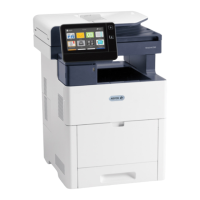
a. To check the cross process direction magnification: measure the 200mm line run-
ning from near LE1 to near LE3. Check that the dimension is 200mm +/- 1mm (7.9
inches +/- 0.04 inch). Refer to Figure 1.
Figure 1 Cross process direction magnification
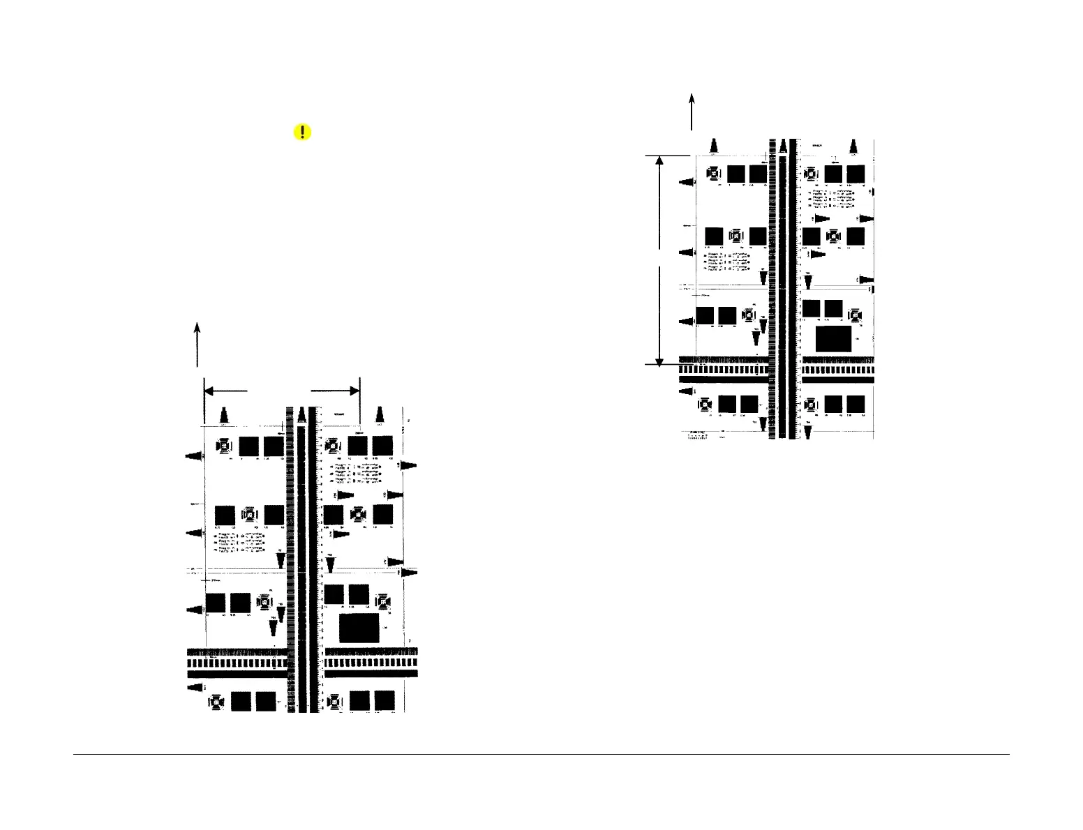
b. To check the in process direction magnification: measure the 300mm line running
from near LE1 to the trail edge of the 1.8lp ladder. Check that the dimension is
300mm +/- 1mm (11.8 inches +/- 0.04 inch). Refer to Figure 2.
Figure 2 In process direction magnification
3. If either measurement is not in specification, perform the relevant Adjustment.
Adjustment
Cross Process Direction Magnification
1. Enter dC131. Change the value of NVM location 715-702 to correct cross process direc-
tion magnification:
• Increase the value to increase the cross process direction image size.
• Decrease the value to decrease the cross process direction image size.
NOTE: An increment of 1 in NVM = 0.1%.
2. Repeat the Check.
In Process Direction Magnification
1. Enter dC131. Change the value of NVM location 715-051 to correct cross process direc-
tion magnification:
• Increase the value to increase the in process direction image size.
• Decrease the value to decrease the in process direction image size.
NOTE: An increment of 1 in NVM = 0.1%.
2. Repeat the Check.
Lead edge
200mm +/- 1mm
(7.9 inches +/- 0.04 inch)
Lead edge
300mm +/- 1mm
(11.8 inches +/-
0.04 inch)
 Loading...