April 2017
4-116
Xerox® VersaLink® B7025/B7030/B7035 Multifunction Printer
REP 13.17, REP 13.18
Launch Issue
Repairs and Adjustments
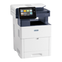
13. Install the brass bearing and E-ring onto the front of the eject roll shaft (1), Figure 20.
Figure 20 Eject roll shaft front components
14. Perform the remainder of the replacement procedure in reverse of the removal procedure.
REP 13.18 Crease Assembly
Parts List on PL 13.35
Removal
WARNING
Switch off the electricity to the machine. Refer to GP 10. Disconnect the power cord
from the customer supply while performing tasks that do not need electricity. Electricity
can cause death or injury. Moving parts can cause injury.
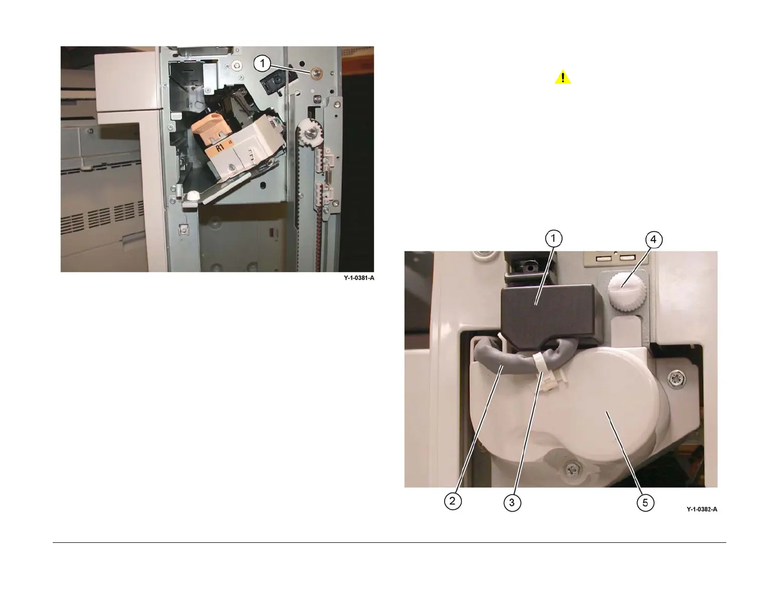
1. Remove the crease assembly, Figure 1:
a. Open the finisher front door.
b. Remove the guard (1).
c. Disconnect the cable (2).
NOTE: . Pull out the cable tie (3) to obtain additional slack in the cable.
d. Remove the thumbscrew (4).
e. Pull out the crease assembly (5).
Figure 1 Crease assembly removal
 Loading...