April 2017
4-73
Xerox® VersaLink® B7025/B7030/B7035 Multifunction Printer
REP 12.13, REP 12.14
Repairs and Adjustments
Launch Issue
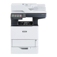
Figure 2 Upper chute assembly removal
Replacement
The replacement is the reverse of the removal procedure.
NOTE: Ensure that the paper guides on the upper chute, PL 12.13 Item 4 are not folded back
on top of the exit roll assembly.
REP 12.14 Finisher PWB
Parts List on PL 12.14
Removal
WARNING
Switch off the electricity to the machine. Refer to GP 10. Disconnect the power cord
from the customer supply while performing tasks that do not need electricity. Electricity
can cause death or injury. Moving parts can cause injury.
1. If possible, record the current software level by either:
• Printing the configuration report, GP 14.
• From the user interface Home screen, touch Device, then About. Scroll down to view
the Software Version.
2. Remove the integrated office finisher, REP 12.1.
3. Turn over the integrated office finisher.
4. Remove the bottom cover, PL 12.06 Item 1.
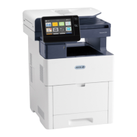
5. Remove the finisher PWB, Figure 1:
a. Disconnect 12 connectors (1).
b. Remove four screws (2).
c. Remove the finisher PWB (3).
Figure 1 Finisher PWB removal
Replacement
1. The replacement is the reverse of the removal procedure.
2. Check the machines current software level against the software level recorded prior to
installation of the new finisher PWB. If necessary, reload the software, GP 4.
 Loading...