April 2017
4-156
Xerox® VersaLink® B7025/B7030/B7035 Multifunction Printer
REP 60.8
Launch Issue
Repairs and Adjustments
Replacement
1. The replacement is the reverse of the removal procedure.
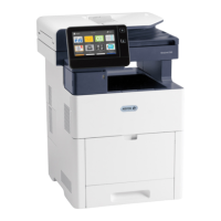
2. When installing the print head assembly, fit the frame hole into the block (1), Figure 6.
Figure 6 Block
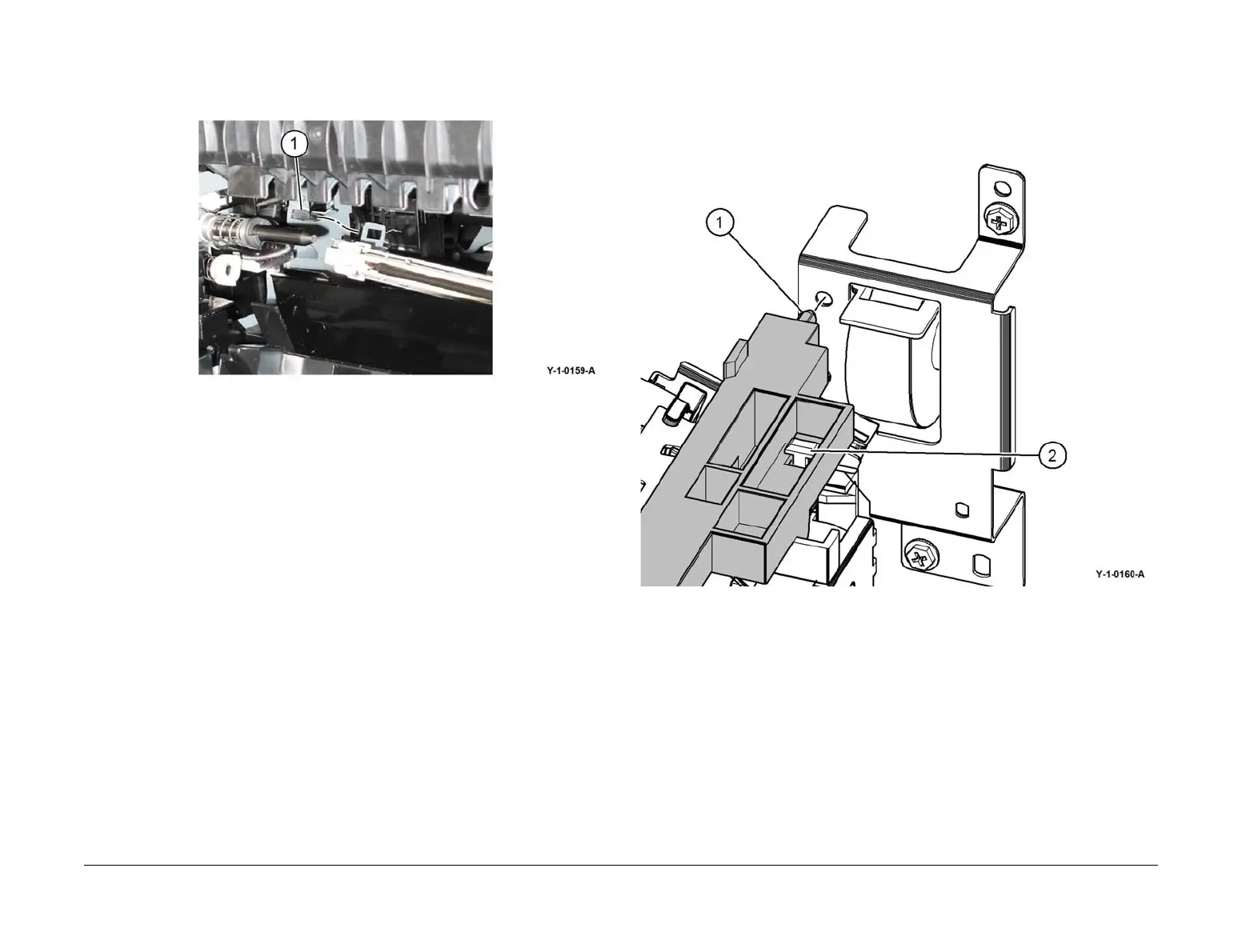
3. When installing the CRU upper guide assembly, Figure 7.
a. Align the boss (1) with the hole.
b. Align the slot (2) in the CRU upper guide assembly with the T- shaped alignment
post of the conductor housing and push forward to ensure correct contact between
the AC spring coil and the metal contact of the CRU upper guide assembly.
Figure 7 Boss
 Loading...