April 2017
4-16
Xerox® VersaLink® B7025/B7030/B7035 Multifunction Printer
REP 3.1
Launch Issue
Repairs and Adjustments
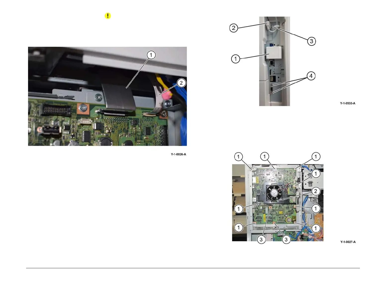
CAUTION
The FFC LED cable is secured by a clamp. Carefully lift both ends of the cable clamp simulta-
neously to release the cable.
11. Carefully disconnect the CCD ribbon cable (1) and the FFC LED cable (2), Figure 10.
Figure 10 Cables
12. Disconnect the connectors and fittings from side of ESS PWB, Figure 11.
a. If fitted, remove the wireless dongle (1).
b. Disconnect the USB cable (2).
c. Remove screw for the USB connector (3).
d. Remove screws for the D-type connector (4).
Figure 11 ESS PWB side connectors
13. Remove the ESS PWB, Figure 12:
a. Remove eight screws (1).
b. Remove the ESS fan (2).
c. For machines without an HDD, remove both screws (3).
Figure 12 ESS PWB removal
 Loading...