April 2017
4-22
Xerox® VersaLink® B7025/B7030/B7035 Multifunction Printer
REP 3.2
Launch Issue
Repairs and Adjustments
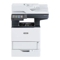
16. Remove two screws (1), Figure 13.
Figure 13 Lower left screws
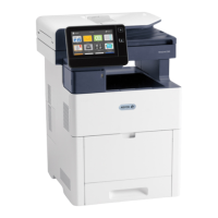
CAUTION
For machines with a fax, the USB cable and connector are still secured by the clamp. Do not
forcibly pull the ESS PWB chassis assembly.
17. Remove two screws (1), then the ESS PWB chassis assembly (2), Figure 14:
Figure 14 ESS PWB chassis assembly removal
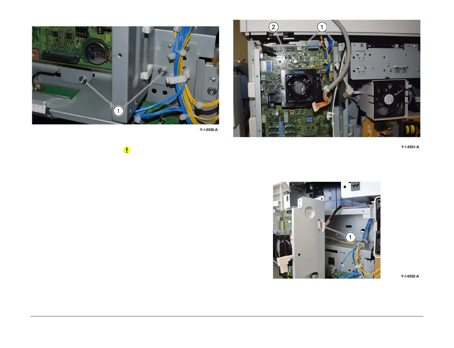
18. If the machine has a fax installed, release the USB cable and connector from the clamp
(1), Figure 15.
Figure 15 USB cable and connector
Replacement
The replacement is the reverse of the removal procedure.
 Loading...