PROCEDURE
1 Clean all surfaces that touch on the bearing cover and bearing girder.
2 Make sure that the oil bore in the bearing cover is clear.
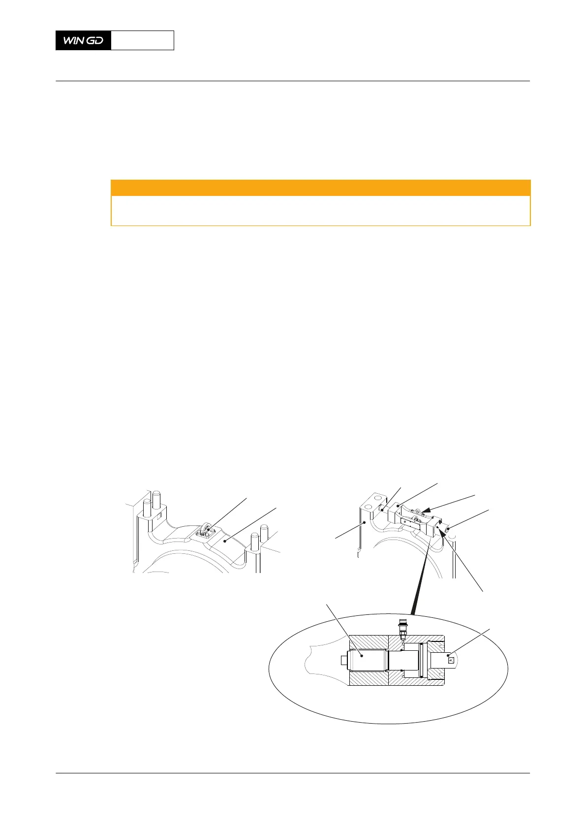
3 Attach the lug (001, Figure 6-6) to the bearing cover (002).
WARNING
Injury Hazard: Do not use the thrust device to lift the bearing cover. Injury to personnel
can occur.
4 Put the thrust device (004) in position on the bearing cover (002).
NOTE: Use the lifting plate (005) only to move and install the thrust device (004).
5 Move the lifting plate (005) to its stowage position as shown.
6 Open the vent screw (007) and make sure that the piston (006) is fully engaged.
7 Make sure that the tappet (008) and the piston (006) fully engage with the cutouts in the
bearing cover (002).
8 Operate the HP oil pump.
9 When oil that has no air flows out, close the vent screw (007).
10 Slowly increase the pressure to 1500 bar.
11 Manually tighten the screw (008).
12 Open the relief valve on the HP oil pump to release the pressure to zero.
13 Remove the HP hose from the thrust device (004).
Fig 6-6 Thrust device
00614
001
002
004003
002
008
006
006
005
007
X72DF
AA00-1132-00AAA-720A-A
Maintenance Manual Main bearing - install the cover
Winterthur Gas & Diesel Ltd.
- 111 - Issue 002 2020-10