Tab 8-1 Maximum permitted difference in mm
Engine type Difference
X35, X35-B 0.03
X40, X40-B
X40DF
0.03
X52
X52DF
0.04
X62, X62-B
X62DF
0.04
X72, X72-B
X72DF
0.05
X82, X82-B
X82DF
0.06
X92, X92-B
X92DF
0.06
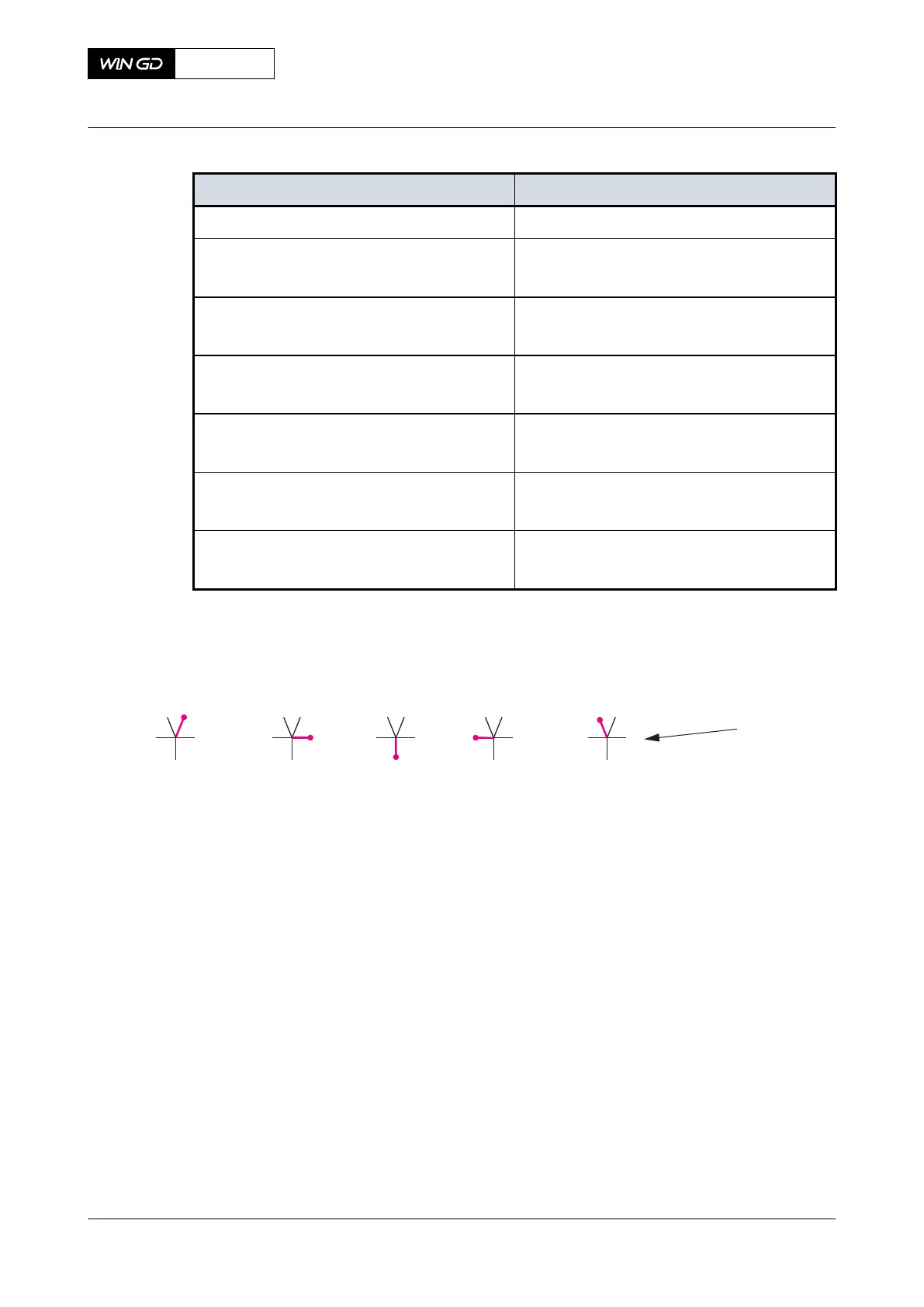
Fig 8-3 Definitions of positions
001
1 2 3 4 5
TDC ES ES BDC FS TDC FS
Legend
001 Dial gauge position
4.11 Do also the visual inspections that follow:
•
Visually do a check of the crank and the bedplate for unwanted material.
•
Visually do a check of the edge for unusual colors.
5 Do Step 4 again for the other cranks.
6 For each crank calculate the vertical deviation d
vert
as follows:
6.1 Calculate the average value d
1’
for position 1 and 5 with the formula
d
1’
= [d
1
+ d
5
] / 2.
6.2 Calculate the vertical deviation d
vert
with the formula d
vert
= d
3
- d
1’
.
7 For each crank calculate the horizontal deviation d
hor
with the formula d
hor
= d
2
- d
4
.
X72DF
AA00-3103-00AAA-360A-A
Maintenance Manual Crankshaft - do a check of the crank deflection
Winterthur Gas & Diesel Ltd.
- 353 - Issue 002 2020-10