PROCEDURE
1 Install the guide bush.
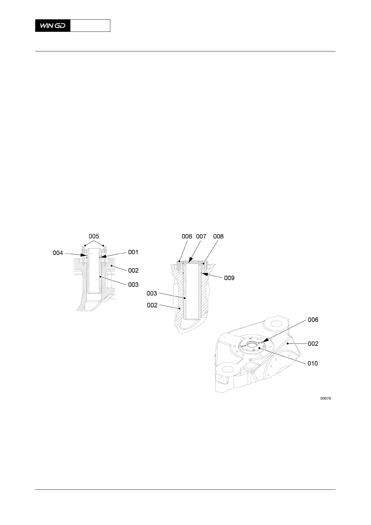
1.1 Clean the bore in the valve cage (002, Figure 7-65).
1.2 Clean the guide bush (003).
1.3 Make sure that the oil bores (004) in the guide bush (003) are clear.
1.4 Put oil on the new O-ring (009) and the guide bush (003).
1.5 Put the O-ring (009) on the guide bush (003).
1.6 Put the guide bush (003) in position in the valve cage (002).
1.7 Put the two jack screws (005) into the valve cage (002).
1.8 Turn the jack screws (005) to push the guide bush (003) fully in to the valve cage
(002).
1.9 Put oil on the rod joint ring (007).
1.10 Put the rod joint ring (007) in position.
Fig 7-65 Guide bush - installation
2 Install the valve spindle.
2.1 Measure the dimensions of the valve spindle (015, Figure 7-66).
2.2 Compare the values with those given in section 3.3 Clearances - general.
2.3 Make sure that the piston joint ring (004) has no damage. If you find damage,
replace with the new piston joint ring.
2.4 Replace all remaining O-rings.
2.5 Put oil on the valve spindle (015).
2.6 Attach the two eye bolts to the valve cage (017).
2.7 Attach the chain to the two eye bolts.
X72DF
AA00-2751-00AAA-710A-A
Maintenance Manual Exhaust valve - assemble
Winterthur Gas & Diesel Ltd.
- 315 - Issue 002 2020-10