Fig 7-25 Electrical connection
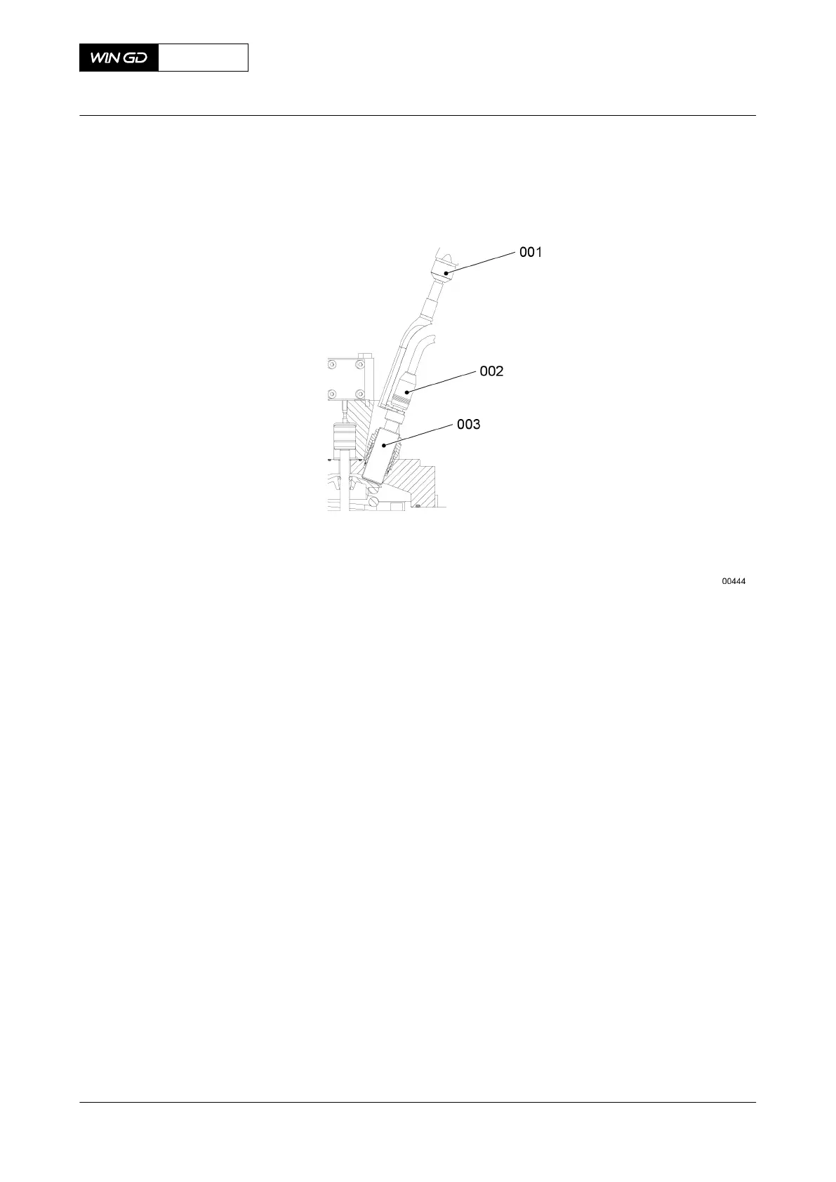
15 Make sure that the compensator (001, Figure 7-26), the O-rings (008), the coupling
flanges and the surface of connecting block and are clean and in good condition.
16 Put the tool in position on the compensator (001) as shown.
NOTE: The disassembly / assembly tool (006) is shorter than the installed length of
the compensator (001).
17 Attach the tool (006) to the flanges of the compensator (001) with the screws (007).
18 Tighten the screws (007).
19 Tighten the bolts (005) at the same time to compress the compensator (001).
20 Continue to tighten the bolts (005) until the compensator (001) is sufficiently
compressed for installation.
21 Make sure that the O-rings (008) are in their correct positions.
22 Put the compensator (001) and tool (006) in position between the connecting block
(004) and the flanges (002).
NOTE: During this step, make sure that the O-rings (008) stay in position.
23 Make sure that the holes in the compensator (001) align with the holes in the flanges
(002).
24 Loosen the bolts (005) at the same time to release the tension of the compensator
(001).
25 Remove the tool (006) from the compensator (001).
26 Put oil on the threads of the screws (003).
27 Attach the compensator (001) to the flanges (002) with the screws (003).
28 Tighten the screws (003).
X72DF
AA00-2140-00AAA-720A-A
Maintenance Manual Gas admission valve - install
Winterthur Gas & Diesel Ltd.
- 222 - Issue 002 2020-10