PROCEDURE
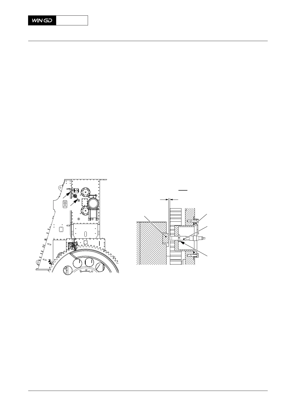
1 Put the proximity sensor (002, Figure 12-18) into the sensor adapter (001).
2 Turn the proximity sensor until the end of the proximity sensor is 3.5 ±0.5 mm from the
mark (004).
3 Tighten the locknut (003).
4 Connect the electrical connection to the proximity sensor (002).
5 On the local control panel, make sure that no failure shows.
6 If applicable, make sure that no failure shows in the control box of the Lenze Drive
system.
NOTE: Different designs have a Lenze Drive system installed. This system has a
control box installed in the control cabinet. The control box shows signal
failures.
Fig 12-18 Proximity sensor - install
I
I
00585
3.5 ±0.5 mm
I - I
ZS5401C - DRVING END
002
ZS5405C - FREE END
003
001
004
CLOSE UP
• None
X72DF
AA00-7762-00AAA-720A-A
Maintenance Manual Electric balancer sensor unit - install the proximity sensor
Winterthur Gas & Diesel Ltd.
- 709 - Issue 002 2020-10