PROCEDURE
1 Do this procedure in the conditions that follow:
•
Related to the intervals given from the owner (related to classification societies)
•
Related to the intervals given from WinGD
•
If temperature alarms of bearings occurred
•
If damage of bearings occurred
•
After the main bearing shells are replaced and again after approximately 100
operation hours
•
If the vessel has hit the sea bed.
2 Prepare the vessel and the engine for the measurement as follows:
2.1 Make sure that the items that follow are sufficiently cool:
•
System oil
•
Cooling water
•
Engine
2.2 Make sure that the vessel floats freely in a horizontal position.
NOTE: You must not do this measurement in the dry-dock.
2.3 Get access to the crankshaft of the engine.
3 Record the general data that follow:
•
Load of the engine
•
Temperature of the engine
•
Temperature of the seawater
•
Temperature of the HT water
•
Temperature of the system oil
•
Draught of the vessel (fore side and aft side)
4 Measure the values for the first crank as follows:
4.1 Operate the turning gear to turn the engine in the direction related to Figure 8-2
until the crank is in the BDC position.
4.2 Continue to operate the turning gear in the same direction until the punch marks
are freely accessible (position 1 in Figure 8-2).
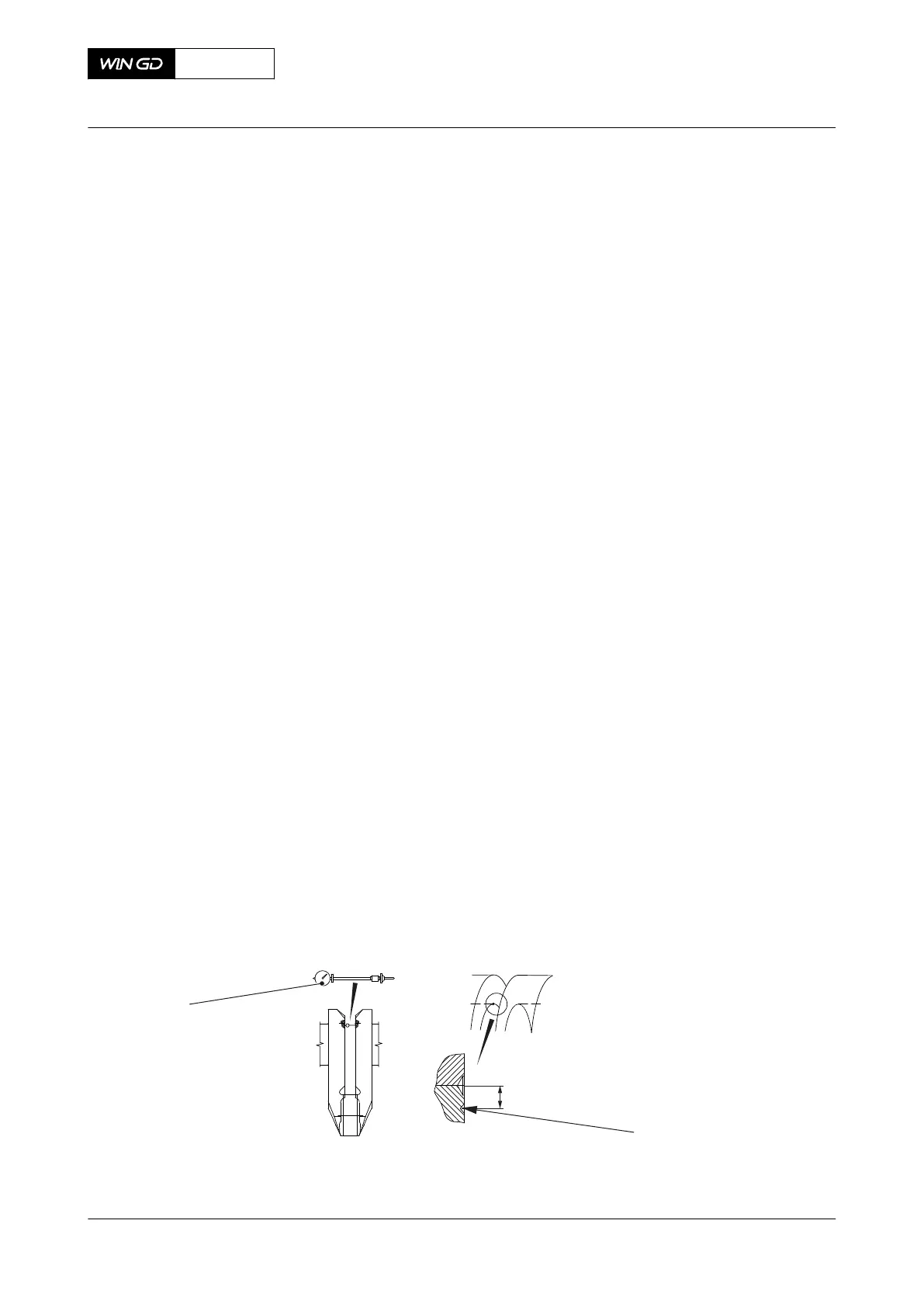
4.3 Put the dial gauge (002, Figure 8-1) next to the connecting rod in the center
punch marks (001). Make sure that the dial gauge (002) goes into the center
punch marks (001).
Fig 8-1 Dial gauge position
4.4 Turn the rod of the dial gauge (002) to apply tension.
4.5 Set the dial gauge (002) to zero.
X72DF
AA00-3103-00AAA-360A-A
Maintenance Manual Crankshaft - do a check of the crank deflection
Winterthur Gas & Diesel Ltd.
- 351 - Issue 002 2020-10