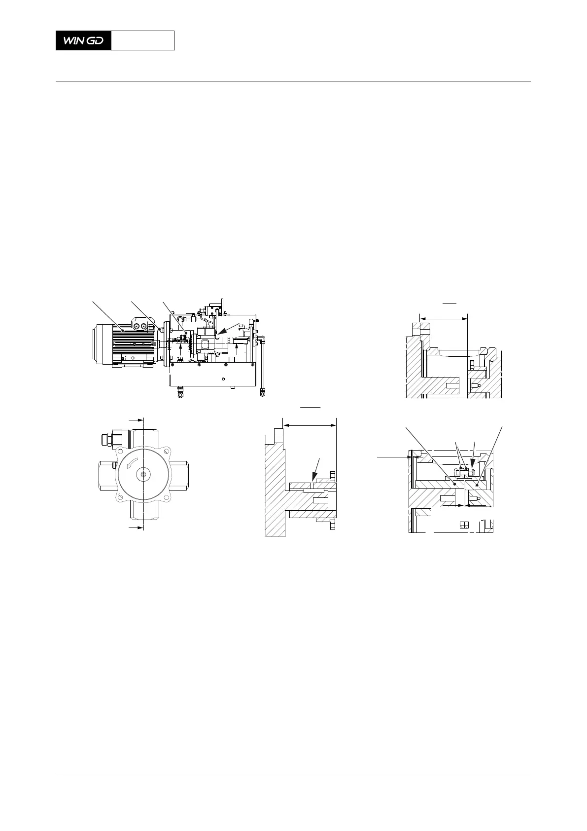
19 Push the flange on the motor shaft until you get a distance of X=3.0 mm.
20 Lock the hubs with an M8 screw (008).
21 Fill the coupling with grease.
22 Attach the electric motor (001) to the connection piece (003) with the four bolts and nuts
(002).
23 Make sure that the distance between the hubs (004, 007) is 3.0 mm.
24 Attach the sleeves together with the screws and nuts (006).
25 Torque the nuts (006) to 36 Nm.
26
Make sure that the sleeves (005) move freely a distance of 1.5
+1.5
0
mm.
Fig 10-5 Pilot fuel supply unit - clearances
001
II
II
002
003
II
I
I
I - I
004
007
006
3.0 mm
008
X - 3.0 mm
X
II - II
005
1.5
+0.3
0
27 Apply NeverSeez NSBT8 to the threads and surfaces that touch of the coupling nuts
(001, Figure 10-6).
28 Attach the pilot fuel pressure pipe (002) to the position shown.
29 Torque the two coupling nuts (001) to 30 Nm.
30 Install the pilot fuel return pipe (004).
31 Install the fuel inlet pipe (005).
32 Connect the electrical connection to the electric motor (003).
33 Attach the cover (006) to the pilot fuel supply pump.
X72DF
AA00-5555-00AAA-720A-A
Maintenance Manual Supply unit for pilot fuel - install the pump
Winterthur Gas & Diesel Ltd.
- 548 - Issue 002 2020-10