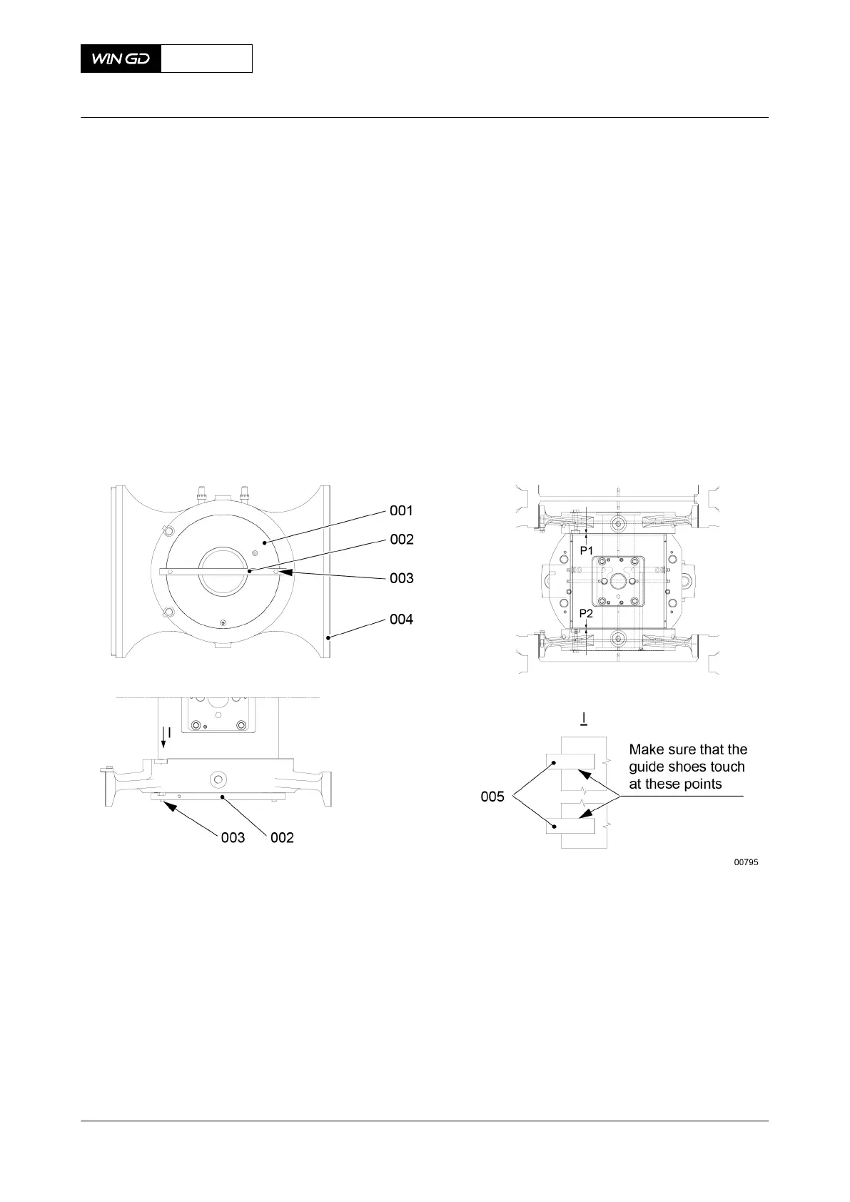
4.1 Attach the tool (005, Figure 8-58) to the crosshead pin (001) with the two screws
(002).
4.2 Tighten equally the two screws (003) to move the crosshead pin (001).
4.3 Make sure that the holding plates of the guide shoes (004) touch at the positions
(006).
4.4 Use the feeler gauge to measure the clearances (P1, P2).
4.5 Loosen the two screws (003).
4.6 Operate the turning gear to move the crankshaft in the astern direction to a
position of between 30° and 35°.
4.7 Tighten equally the two screws (003) to move the crosshead pin (001).
4.8 Do Step 4.2 to Step 4.4 again, then do Step 4.9.
4.9 Remove the tool (005).
Fig 8-58 Dimensions check
CLOSE UP
• None
X72DF
AA00-3326-00AAA-360A-A
Maintenance Manual Crosshead - do a check of the clearances
Winterthur Gas & Diesel Ltd.
- 460 - Issue 002 2020-10