35 Put oil on the threads and surfaces that touch on the bolts (004) of each support (003).
36 Attach the two supports (003) to the columns with the bolts (004).
37 Torque the bolts (004) to the correct value, refer to section 16.1 Tightening instructions.
38 Operate the chain blocks (001, 002, 007)) to lower the crosshead pin on to the supports
(003). Make sure that the two cups (006) engage with the recesses in the crosshead.
39 Tighten the special screws (005).
NOTE: Make sure that the primary load stays on the chain of the spur-geared chain
block (001).
40 Put a wooden chock (010) in position as shown.
41 Operate the lever chain hoists (008, 011) to move the connecting rod (009) to the
exhaust side. Continue until the connecting rod touches the wooden chock (010).
42 Remove the two lever chain hoists (008, 011).
43 Remove the supports (003) as follows:
43.1 Remove the special screw (005).
43.2 Loosen the bolts (005).
43.3 Remove the supports (003).
44 Operate the chain blocks (001, 002, 007) to lower the crosshead pin sufficiently to do
the work.
NOTE: Make sure that the primary load stays on the chain block (001).
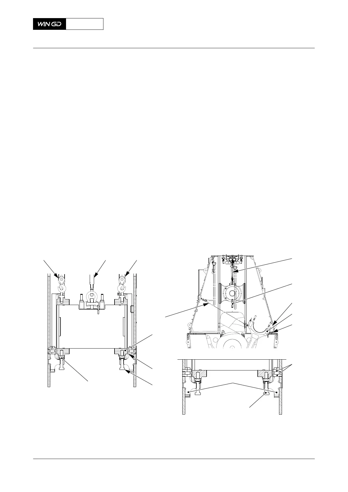
Fig 8-52 Connecting rod - move
001 002
003
004
005
006
001
002
007
003
008
009
011
004
005
003
00747
007
FUEL SIDE
010
45 Remove the two bolts, tab washers and holding plates (004, Figure 8-53) from the guide
shoe (006 or 009).
46 When the crosshead pin (007) is in the second or next to last position, do as follows:
46.1 Attach the two eye bolts (005) to the crosshead pin (007).
X72DF
AA00-3326-00AAA-520A-A
Maintenance Manual Crosshead - remove
Winterthur Gas & Diesel Ltd.
- 451 - Issue 002 2020-10