PROCEDURE
1 Attach the eye bolt (001, Figure 7-62) to the valve spindle (004).
2 Attach the rope to the eye bolt (001) and the engine room crane.
3 Put a thin layer of engineer’s blue paste on the sealing face of the valve spindle (004).
4 Put the valve spindle (004) in position in the valve guide bush.
5 Put the wooden block (003) on the valve spindle (004).
6 Tap the wooden block (003) with the hammer (002) three or four times.
NOTE: During this step, do not turn the valve spindle (004) because this can cause
the sealing faces to catch.
7 Use the feeler gauge to do a check of the clearance X between the sealing faces of the
valve spindle (004) and valve seat (005), refer to Table 7-2 - Exhaust valve, clearance X.
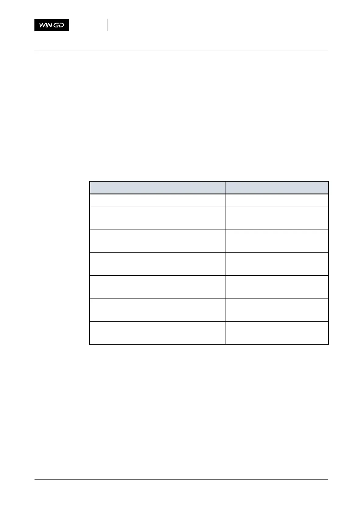
Tab 7-2 Exhaust valve, clearance X
Engine type Clearance X [mm]
X35, X35-B 0.005 to 0.020
X40, X40-B
X40DF
0.005 to 0.020
X52
X52DF
0.033 to 0.062
X62, X62-B
X62DF
0.054 to 0.070
X72, X72-B
X72DF
0.054 to 0.070
X82, X82-B
X82DF
0.120 to 0.150
X92, X92-B
X92DF
0.120 to 0.150
8 Remove the valve spindle (004) from the guide bush.
9 Do a check of the engineer’s blue paste. The paste must only show on the inner part of
the full circumference of the valve spindle.
X72DF
AA00-2751-01AAA-360A-A
Maintenance Manual Exhaust valve - do a check of the seat
Winterthur Gas & Diesel Ltd.
- 305 - Issue 002 2020-10