4.6 Operate the turning gear in the same direction to move the crank to each
position of the dial gauge (001, Figure 8-2).
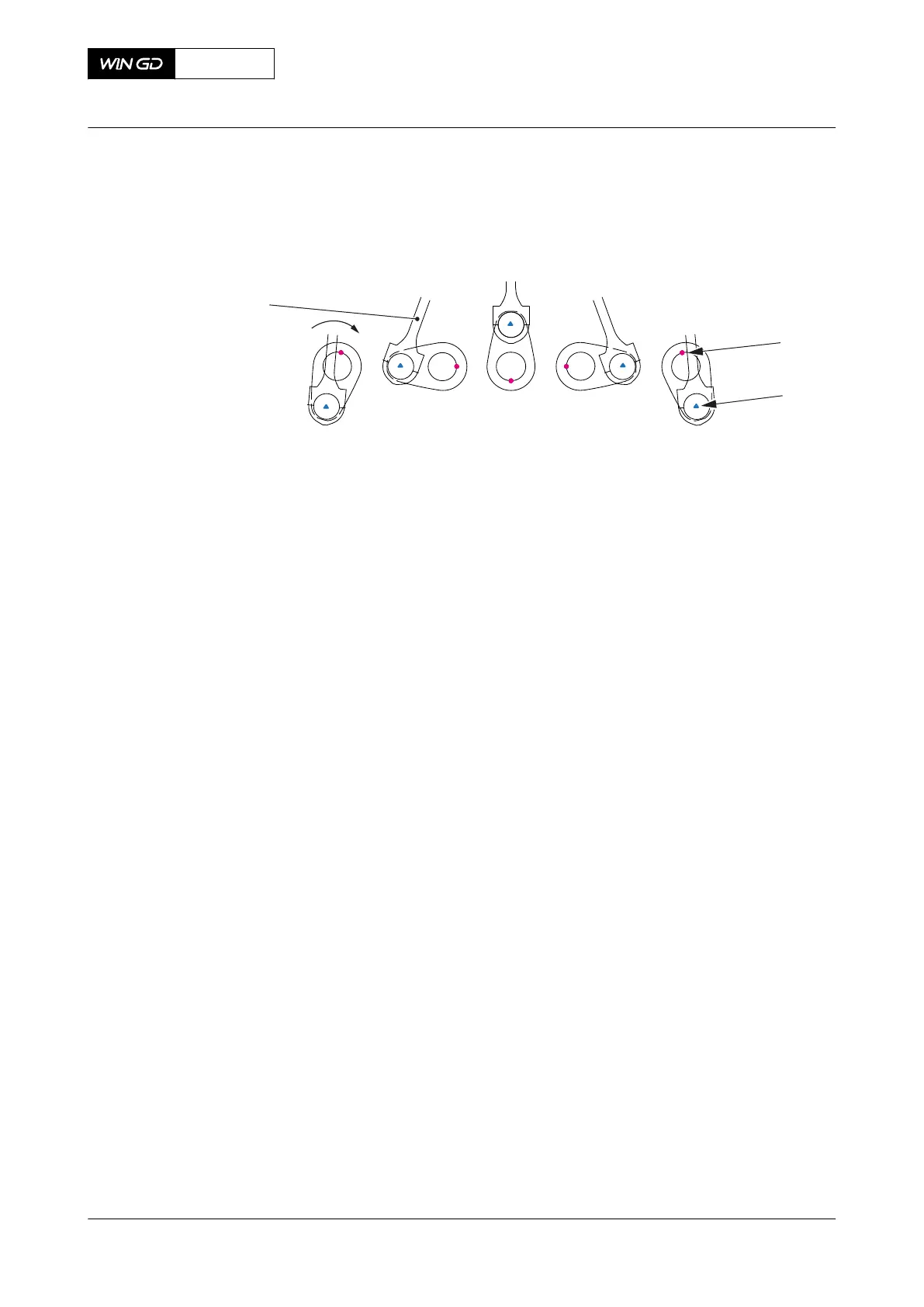
Fig 8-2 Crank positions for clockwise direction
Legend
001 Dial gauge position 003 Connecting rod
002 Crank pin position
NOTE: For counterclockwise rotation, start at position 5.
4.7 For cranks n to n-1 or n-2 (related to the number of cylinders of the engine)
operate the turning gear in the opposite direction a short time to release
pressure between pinion and flywheel.
4.8 At each position, record the indication on the dial gauge. For the last position
make sure that the connecting rod (003) does not touch the dial gauge.
4.9 At position 3 also visually check the clearance of the connecting rod bearing.
4.10 If the difference between positions 1 and 5 is more than the value related to
Table 8-1 - Maximum permitted difference in mm, you must do the measurement
again.
NOTE: For the definitions for positions 1 to 5 refer to Figure 8-3.
X72DF
AA00-3103-00AAA-360A-A
Maintenance Manual Crankshaft - do a check of the crank deflection
Winterthur Gas & Diesel Ltd.
- 352 - Issue 002 2020-10