PROCEDURE
1 Prepare the equipment as follows:
1.1 Make sure that the work area is clean.
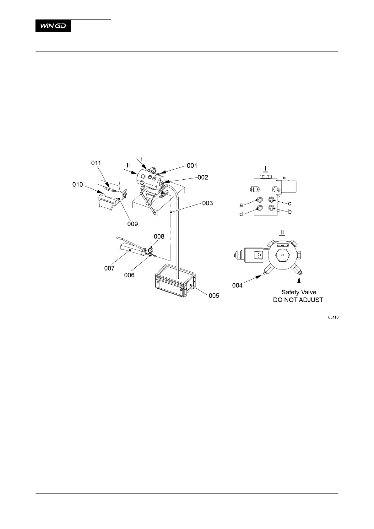
1.2 Put protection (010, Figure 10-24) around the PCV test block (009).
Fig 10-24 PCV - do a check
1.3 Put the test block (009) in a bench vice.
1.4 Make sure that the sealing surfaces of the pressure control valve (PCV) and the
test block (009) are clean and have no damage.
1.5 Put the PCV in position on the test block (009).
1.6 Put oil on the threads of the screws (001).
1.7 Put the screws (001) in position in the PCV.
1.8 Tighten the screws (001) in the sequence given in view I, refer to section 16.1
Tightening instructions.
1.9 Attach the flexible tube (part of the test block 009) to the PCV outlet (002). Put
the other end of the flexible tube into an applicable container (005).
1.10 Connect the HP oil pump (007), the pressure gauge (008) and the HP hose
(003) to the test block (009).
1.11 Identify each of the two pressure control set screws.
1.12 On the set-point adjustment valve (SAV) (004), loosen the locknut.
1.13 Fully loosen the SAV (004) to minimum.
2 Adjust the PCV as follows:
2.1 Operate the HP oil pump (007).
2.2 Adjust the SAV (004) to get a value of 100 bar.
X72DF
AA00-5562-00AAA-360A-A
Maintenance Manual Fuel rail - do a check of the pressure control valve
Winterthur Gas & Diesel Ltd.
- 587 - Issue 002 2020-10