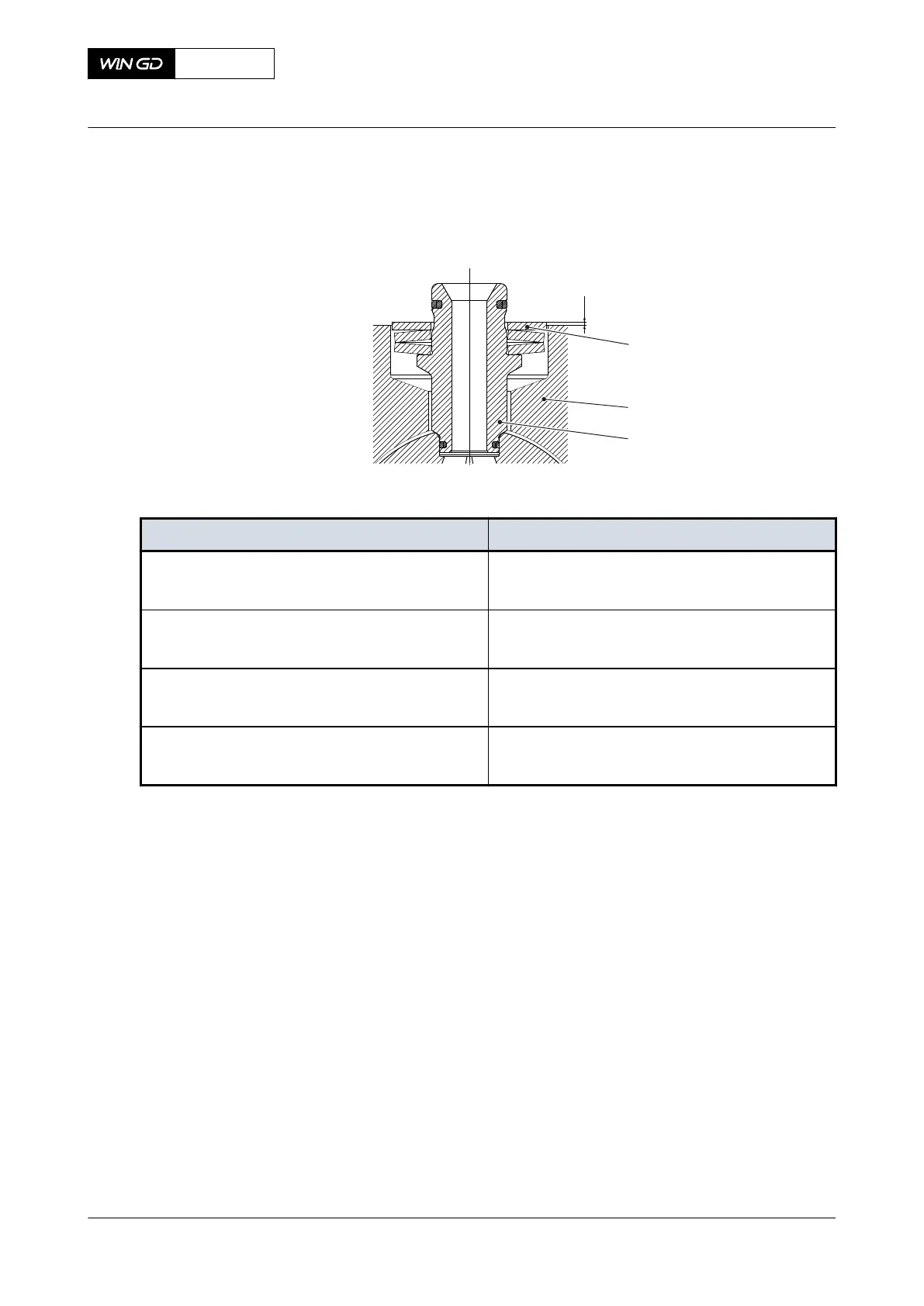
6 Make sure that the distance X (Figure 10-39) between the washer (001) and the holder
(002) is in the correct range, refer to Table 10-1 - Distance X for VCU.
Fig 10-39 Connection piece of VCU
Tab 10-1 Distance X for VCU
Engine type Distance X [mm]
X52
X52DF
2.5 +-0.5
X62, X62-B
X62DF
2.5 +-0.5
X72, X72-B
X72DF
2.5 +-0.5
X92, X92-B
X92DF
4.2 +-0.5
7 If the distance X is not in the correct range, for example if the sealing surface of the
connection piece (003) has changed, machine the washer (001) to get the correct
distance X.
8 Carefully put the VCU (005, Figure 10-38) in position on the holder (006).
9 Apply oil to the threads of the screws (004).
10 Tighten with your hand the crews (004).
11 In the sequence given, torque the screws (004) to the correct value, refer to section 16.1
Tightening instructions.
12 Install the supply pipe (008) to the VCU (005).
13 Install the return pipe (001) to the VCU (005).
14 If the VCU (005) installed at the driving end of the servo oil rail (007), also install the HP
hose (002) to the VCU (005).
15 Carefully attach the 4/2-way solenoid valve (003) to the VCU (005).
16 Torque the screws of the 4/2-way solenoid valve (003) to the correct value, refer to
section 16.1 Tightening instructions.
17 Connect the electrical connection to the 4/2-solenoid valve (003).
X72DF
AA00-5612-00AAA-720A-A
Maintenance Manual Exhaust valve control unit (VCU) - install
Winterthur Gas & Diesel Ltd.
- 620 - Issue 002 2020-10