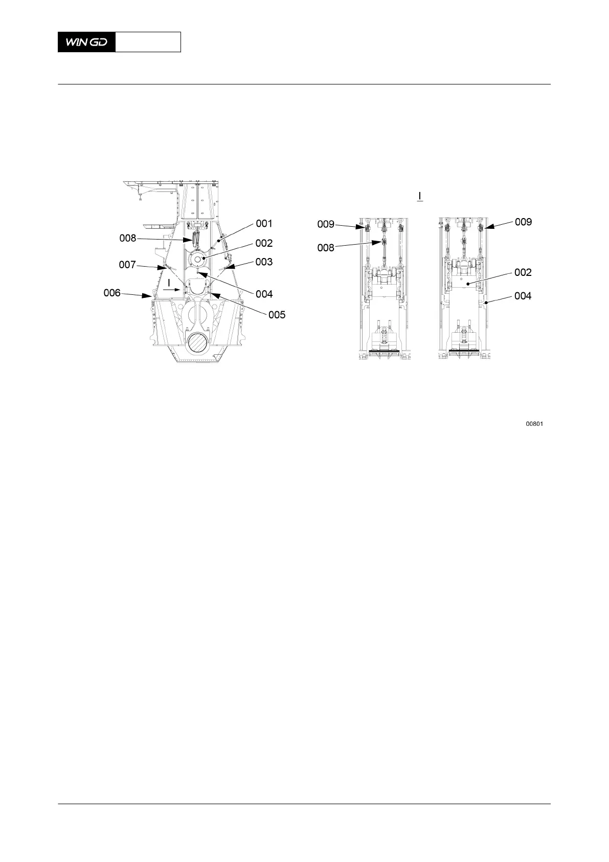
Fig 8-37 Crosshead - lower
24 Put the round nuts (002, Fig. 9) on the elastic studs (001).
25 Use a round bar to tighten equally the round nuts (002).
26 Measure the distances (X1, X2) between the edges of the bearing shells and the
connecting rod (003).
27 For a new bearing shell the clearance must be X1+X2 = 0.45±0.04 mm.
28 Apply tension to the elastic studs (002), refer to section 4.2 Tighten a round nut with a
pre-tensioner.
29 Attach the piston to the crosshead, refer to section 8.7.7 Piston - install.
30 Remove the oil inlet pipe (002, Figure 8-38).
31 Attach the flange (003) to the support (001).
32 Attach the hose (004) to the flange (003).
33 Fill the lubricating pump (005) with steam-engine cylinder oil (see Table 8-5 - ISO VG
1000/1500 suppliers).
34 Operate the lubricating pump (005) until oil flows from the sides of the bearing.
NOTE: Do Step 34 weekly if the engine does not operate for some weeks.
35 Before you operate the engine do Step 35.1 to Step 35.4:
35.1 Make sure that the hose (004) has no pressure.
35.2 Remove the hose (004) from the flange (003).
35.3 Remove the flange (003).
35.4 Install the oil inlet pipe (003) to the support (001).
NOTE: The steam-engine cylinder oil can stay in the oil system.
X72DF
AA00-3303-02AAA-720A-A
Maintenance Manual Connecting rod - install the top end bearing
Winterthur Gas & Diesel Ltd.
- 423 - Issue 002 2020-10