PROCEDURE
1 Measure the clearance of the guide shoe and guide way as follows:
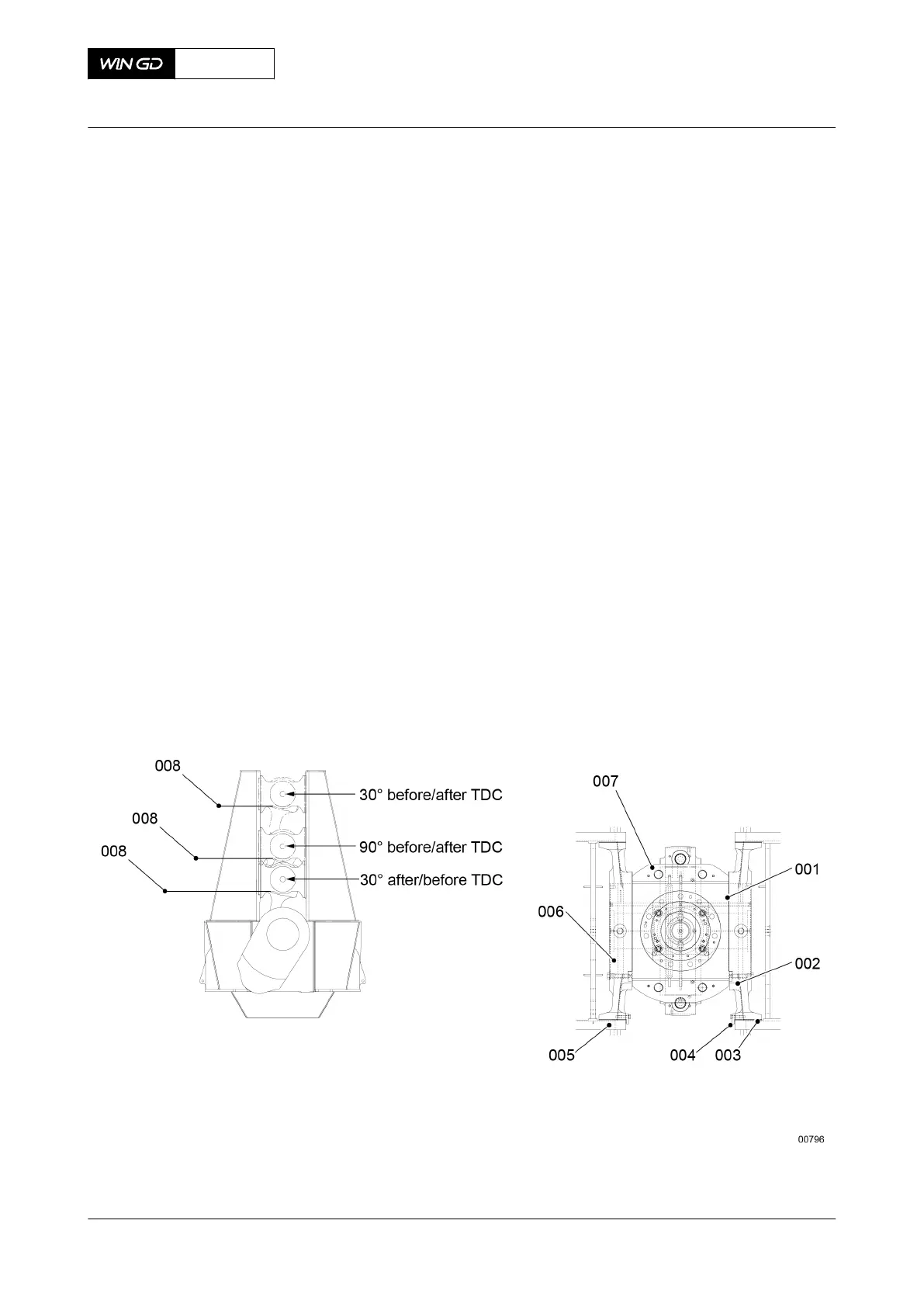
1.1 Make sure that the related crank pin is in a position so that the guide shoes
(006, Figure 8-57) touch the guide ways (004) on the fuel side (or the exhaust
side).
1.2 Operate the turning gear to move the crank to the top position (30° before/after
TDC).
1.3 Measure the clearance (003) between the guide shoe (006) and the guide way
(004).
NOTE: The clearance (003) is applicable for the full length of the guide way
(004) and measured at position (008).
1.4 Operate the turning gear to move the crank to the position (90° before/after
TDC).
1.5 Do Step 1.3 again.
1.6 Operate the turning gear to move the crank to the top position (30° after/before
TDC).
1.7 Do Step 1.3 again.
2 Measure the full lateral clearance (001) between the top end bearing (007) and the
guide shoes (006).
3 Measure the radial clearance (002) between the guide shoe (006) and the crosshead
pin at all positions of the crosshead.
Fig 8-57 Clearance checks
4 Measure the clearance of the crosshead as follows:
X72DF
AA00-3326-00AAA-360A-A
Maintenance Manual Crosshead - do a check of the clearances
Winterthur Gas & Diesel Ltd.
- 459 - Issue 002 2020-10