PROCEDURE
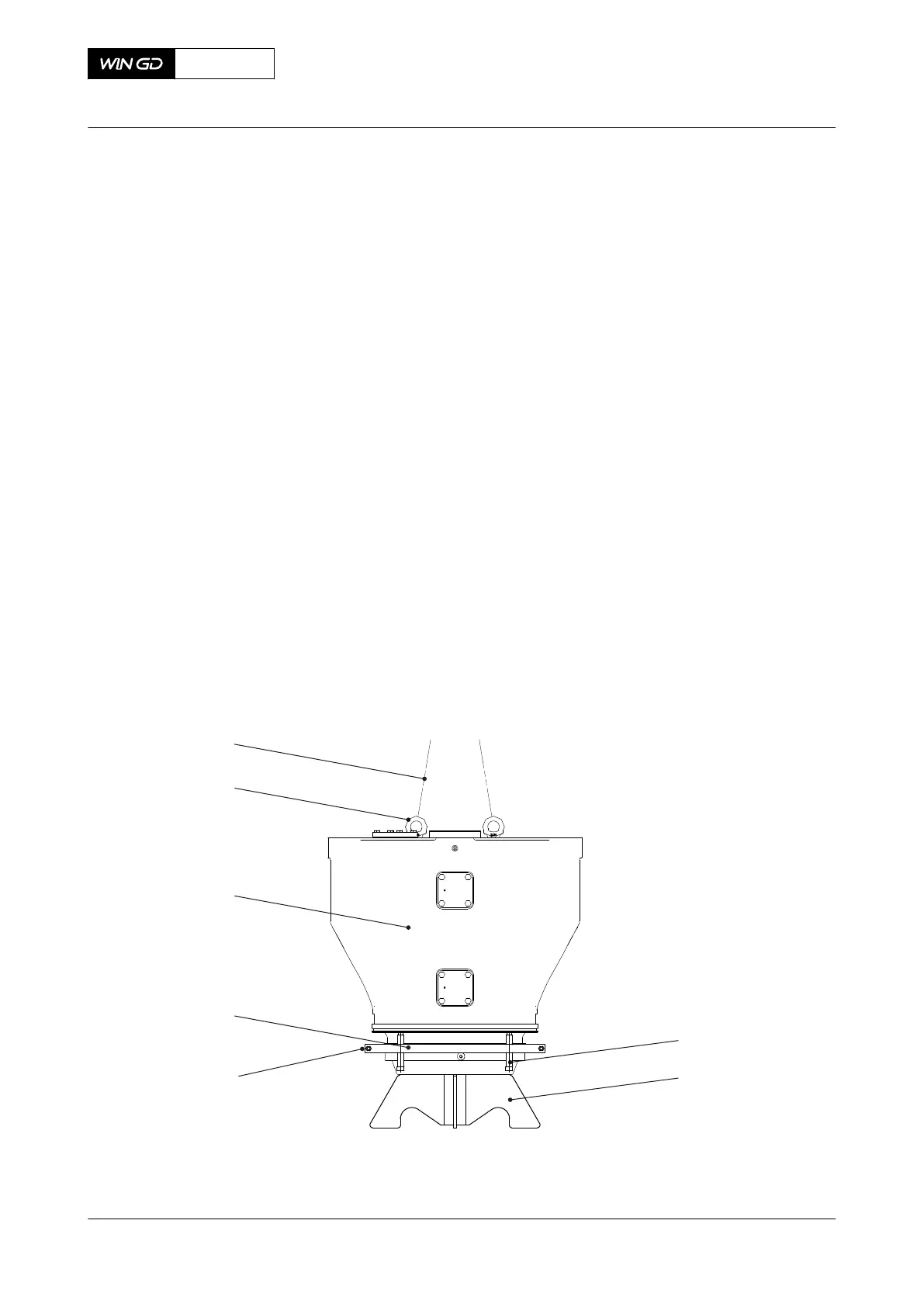
1 Put the assembly tool (002, Figure 7-61) on an applicable surface.
2 Attach two eye bolts (006) on the valve cage (005).
3 Attach two slings (007) to the eye bolts (006) and to the engine room crane.
4 Operate the engine room crane to lift the valve cage (005).
5 Remove and discard the O-ring of the valve seat.
6 Operate the engine room crane to move the valve cage (005) onto the assembly tool
(002).
7 Keep tension on the slings (007).
8 Attach the valve seat dismantling device (004) to the valve seat as follows:
8.1 Remove the two bolts (003) of the valve seat dismantling device (004).
8.2 Put the two halves in the correct position.
8.3 Tighten the two bolts (003).
9 Tighten equally the four lifting screws (001) a few turns to lift the valve cage (005).
10 Operate the engine room crane to keep tension on the slings (007).
11 Do Step 9 and Step 10 again until the valve seat is free.
12 Operate the engine room crane to move the valve cage (005) onto an applicable
wooden support.
13 Remove the valve seat dismantling device (004).
14 Remove and discard the O-ring of the valve seat.
Fig 7-61 Valve seat - remove
X72DF
AA00-2751-01AAA-520C-A
Maintenance Manual Exhaust valve - remove the seat (with new tool)
Winterthur Gas & Diesel Ltd.
- 301 - Issue 002 2020-10