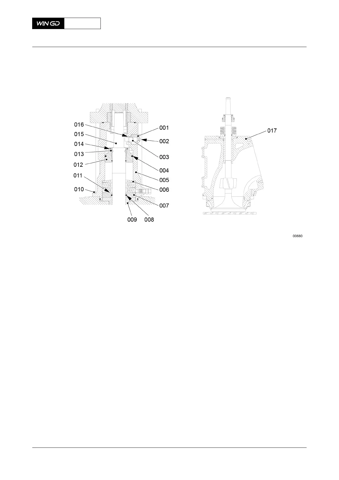
Fig 7-66 Valve spindle - installation
3.12 Attach the engine room crane to the eye bolt (001, Figure 7-67).
3.13 Operate the engine room crane to lift and lower the top housing (003) on to the
bottom housing (006).
3.14 Attach the nuts (004) to the elastic studs (005).
3.15 Torque symmetrically six nuts (004) to the related value, refer to section 16.1
Tightening instructions.
4 Set the damper.
NOTE: You set the damper (002) only after you replace a valve spindle or a valve
seat, or after the grinding procedure of one of the seating faces.
4.1 Remove the damper (002).
4.2 Make sure that the bores (009) in the damper (002) are clear.
4.3 Make sure that the exhaust valve is closed.
4.4 Use the feeler gauge to make sure there is no clearance between the valve plate
and valve seat.
4.5 Use the depth gauge to measure the height H between the top and bottom of the
bore in the top housing.
4.6 Calculate the number of shims T with the formula that follows:
T = H
b
- H ±0.5 [mm]
NOTE: For example for a X72DF engine, if the measured distance H is
163 mm, you must install two shims. Each shim (007) has a thickness
of 1.0 mm (T = 165.2 - 163.0 = 1.8).
4.7 Install the correct quantity of shims.
4.8 Apply Loctite 271 to the threads of the damper (002).
4.9 Install the damper (002).
X72DF
AA00-2751-00AAA-710A-A
Maintenance Manual Exhaust valve - assemble
Winterthur Gas & Diesel Ltd.
- 317 - Issue 002 2020-10