PROCEDURE
1 Prepare the piston for disassembly.
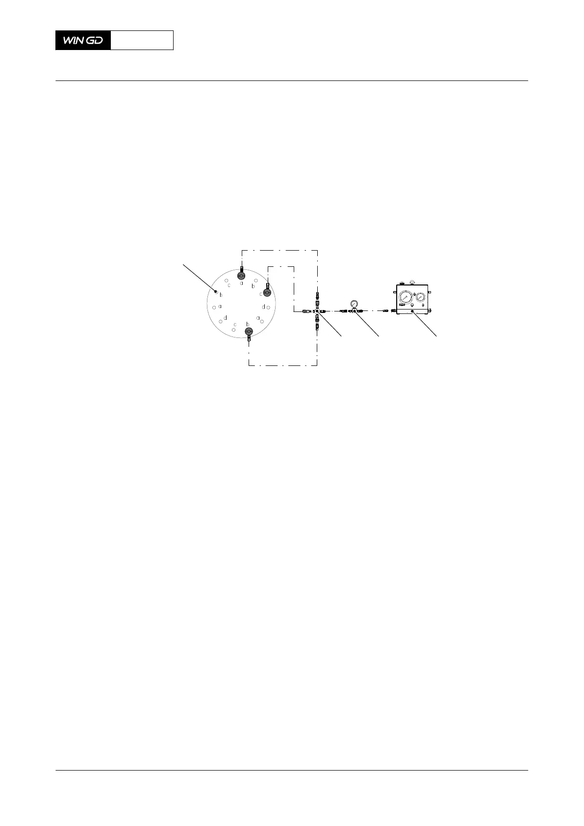
1.1 Attach the hydraulic unit (001, Figure 8-71), the pressure gauge (002), the
distributing piece (003) and the flexible hoses as shown.
1.2 Remove the 11 round nuts (004) in the sequence given, refer to section 4.3
Loosen a round nut with a pre-tensioner.
Fig 8-71 Piston - Preparation before disassembly
2 Put the three jacking screws (002, Figure 8-72) fully into the three tap holes in the top of
the piston rod (003). Make sure that the jacking screws (002) touch the piston head
(001).
3 Tighten equally the three jacking screws (002) until there is a clearance between the
piston head (001) and the piston rod (003).
4 Attach the lifting tool (004) to the piston head (001) with the four screws (006).
5 Torque the bolts to the correct value, refer to section 16.1 Tightening instructions.
6 Attach the engine room crane to the lifting tool (004).
7 Operate the engine room crane to lift the piston head (001).
8 Move the piston head (001) to an applicable area.
9 Remove the three jacking screws (002) from the piston rod (003).
10 Remove the piston skirt (010) from the piston rod (003) as follows:
10.1 Remove the two screws (011).
10.2 Use the jacking screws to separate the piston skirt (010) from the piston rod
(003).
10.3 Lift the piston skirt (010) from the piston rod (003).
NOTE: When you lift the piston skirt (010) make sure that the spring dowel pin
(013) does not catch.
11 Remove the eight screws (012).
12 Use the two jacking screws to remove the spray plate (009) from the piston rod (003).
13 If necessary, remove the pipes (008) and nozzles (007).
14 Remove the lifting tool (004).
15 Do a check of the top surface of the piston head (001), refer to section 8.7.5 Piston
(removed) - do checks of the surface and clearances.
X72DF
AA00-3403-00AAA-530A-A
Maintenance Manual Piston - disassemble
Winterthur Gas & Diesel Ltd.
- 487 - Issue 002 2020-10