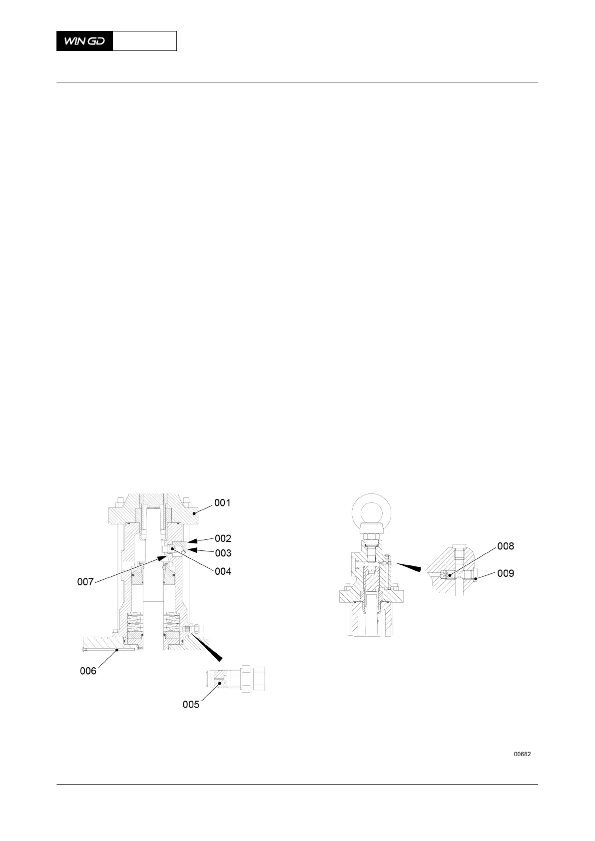
•
The valve stroke sensor (004, Figure 7-68)
•
The transmitter housing (002)
•
The bore and collar in the top housing (001).
5.2 Put oil on the O-ring (007) and on the valve stroke sensor (004).
5.3 Carefully put the O-ring (007) and the valve stroke sensor (004) into the housing.
5.4 Attach the transmitter (004) and transmitter housing (002) to the top housing
(001) with the two screws (003).
5.5 Connect the electrical connection to the valve stroke sensor (003).
6 Do a check of the throttle (008).
6.1 Remove the screw plug (009).
6.2 Remove the throttle (008).
6.3 Make sure that the throttle (008) is clean.
6.4 Put oil on the threads of the throttle (008).
6.5 Put the throttle (008) in the housing.
6.6 Torque the throttle (008) to 20 Nm.
6.7 Attach the screw plug (009).
7 Do a check of the non-return valve (005).
7.1 Remove the non-return valve (005) from the housing (001).
7.2 Make sure that the non-return valve (005) operates correctly.
7.3 Install the non-return valve (005) in the housing (001).
8 Make sure that the oil bore to the valve guide (006) is clear.
Fig 7-68 Valve stroke sensor, throttle and non-return valve
X72DF
AA00-2751-00AAA-710A-A
Maintenance Manual Exhaust valve - assemble
Winterthur Gas & Diesel Ltd.
- 319 - Issue 002 2020-10
 Loading...


