PROCEDURE
1 Remove the bearing cover.
1.1 Operate the turning gear to move the crankshaft until the applicable crank pin
(003, Figure 8-26) is at TDC.
1.2 Lock the turning gear.
1.3 Attach the eye bolts (006) to the bearing cover (004).
1.4 Attach the shackles (009) to the column.
1.5 Attach the lever chain hoist (008) and the lever chain hoists (002) to the
shackles (009).
1.6 Attach the eye bolts (006) to the bearing cover (004).
1.7 Operate the lever chain hoists (002, 008) to put a light tension on their chains.
1.8 Remove the round nuts (001), refer to 4.3 Loosen a round nut with a pre-
tensioner.
1.9 Operate the lever chain hoists (002, 008) to lower the bearing cover (004).
1.10 Do an inspection of the bearing shell (005).
1.11 If the bearing shell (005) is in good condition, do as follows:
1.11.1 Lower the bearing cover (004) to the bottom of the crankcase.
1.11.2 Remove the lever chain hoists (002, 008).
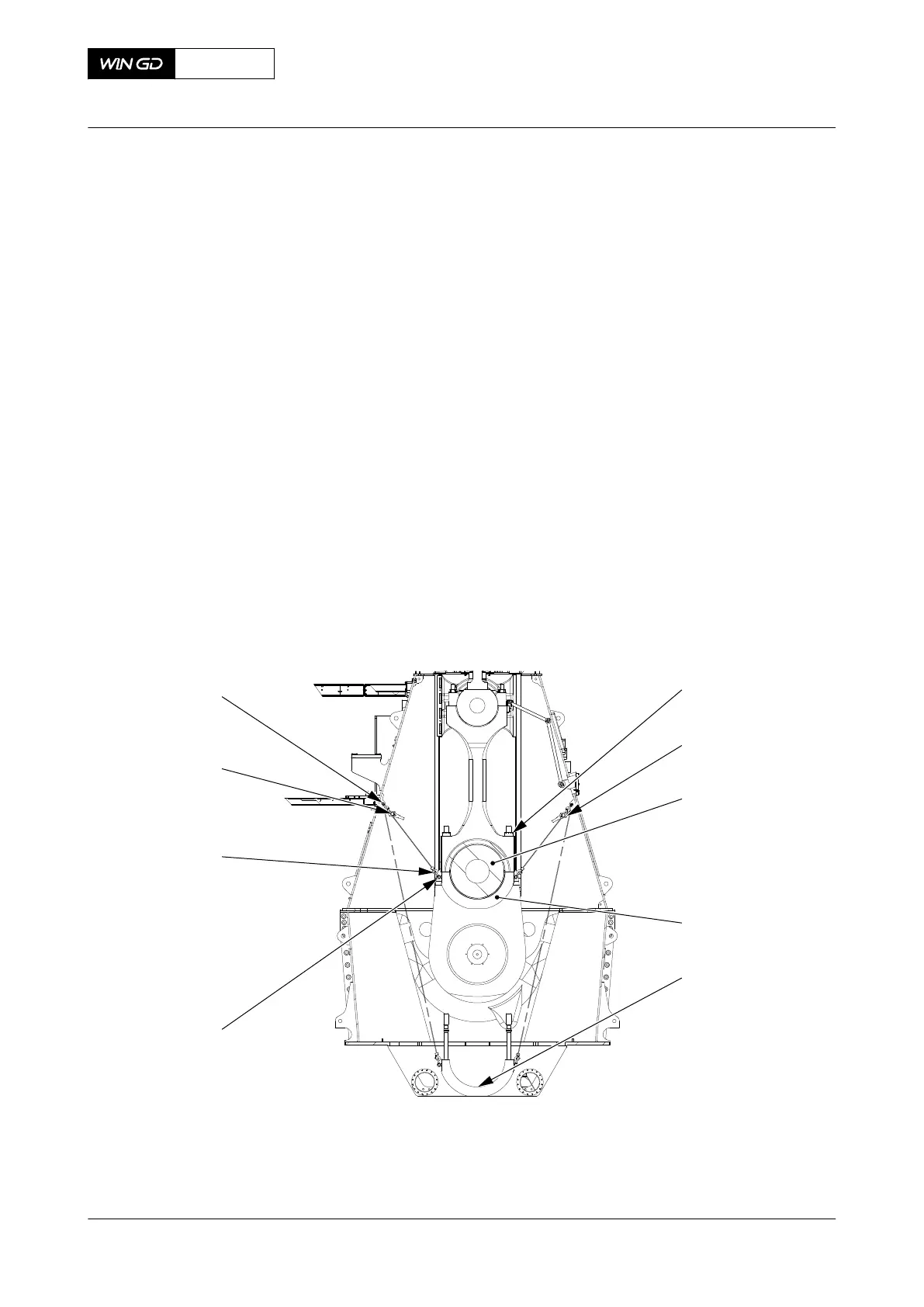
Fig 8-26 Bottom end bearing cover - move
001
002
003
004
005
006
007
008
00770
EXHAUST SIDE
009
1.12 Attach the sling (006, Figure 8-27) to the gallery.
1.13 Attach the spur-geared chain block (005) to the sling (006).
1.14 Install the deviation pipe (003) to the column door frame.
X72DF
AA00-3303-03AAA-520A-A
Maintenance Manual Connecting rod - remove the bottom end bearing
Winterthur Gas & Diesel Ltd.
- 402 - Issue 002 2020-10