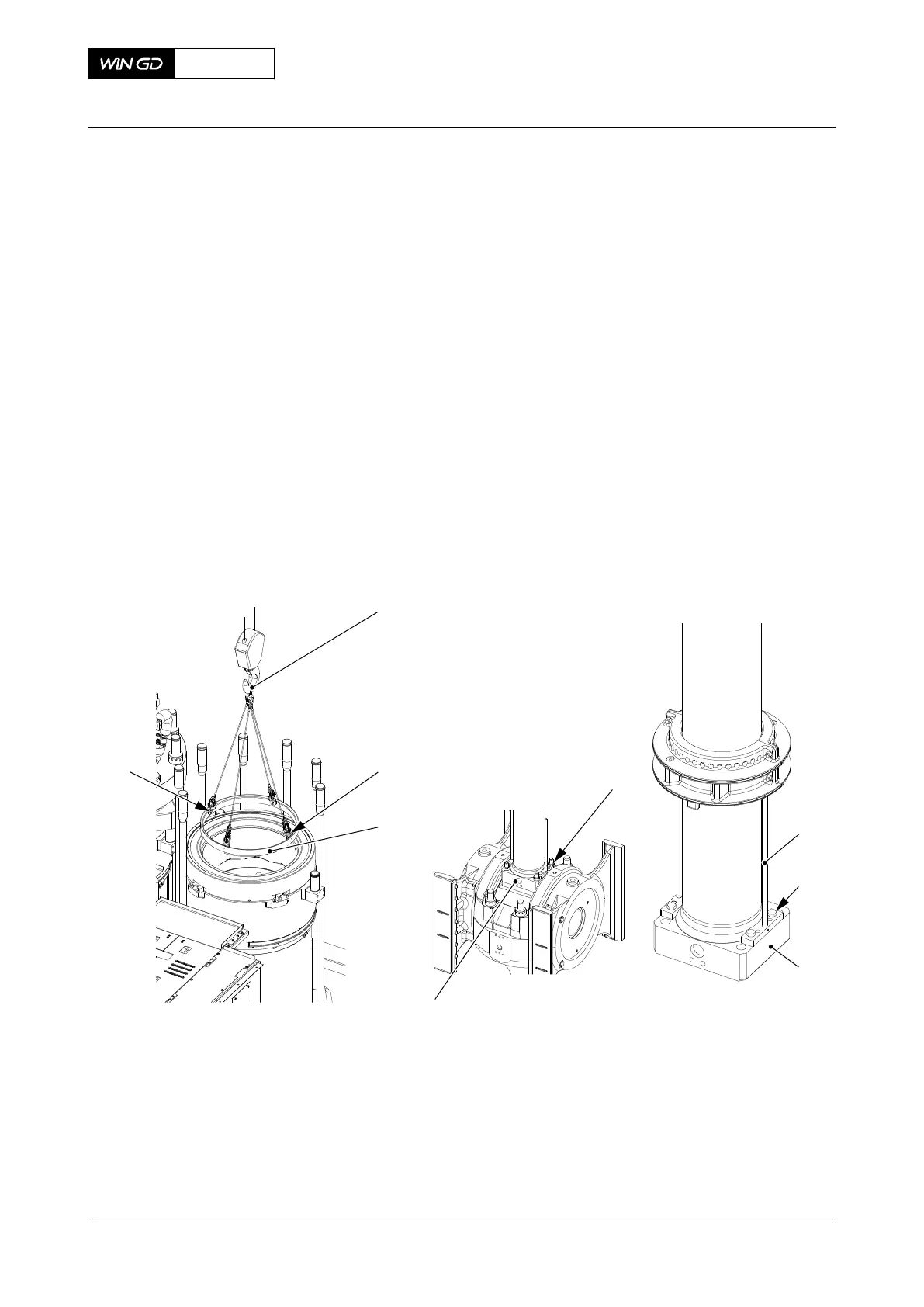
PROCEDURE
1 Attach the four plates (002, Figure 8-68) to the antipolishing ring (003) with the four
screws (004).
2 Connect the engine room crane to the lifting tool (001).
3 Attach the tool 94209 to the antipolishing ring (003).
4 Attach the lifting tool (001) to the tool 94209.
5 Remove the antipolishing ring (003).
6 Look at the area where the piston stroke ends. If there is a wear edge, refer to section
7.1.4 Cylinder liner - grind.
7 Operate the turning gear to move the crank to BDC.
8 Remove the round nuts (005) from the piston rod foot (006), refer to section 4.3 Loosen
a round nut with a pre-tensioner.
9 Attach the two distance holders (007) to the piston rod foot (006) with the screws (008).
10 Remove the knee lever from the crosshead connection.
11 Attach the knee lever in a save position.
Fig 8-68 Piston - Preparation
001
002
003
004
005
006
007
008
006
00779
12 Remove the four bolts (002) from the gland box support (001, Figure 8-69).
13 Operate the turning gear to move the crosshead up until the distance pieces (005) touch
the gland box.
14 Operate the turning gear to push out the gland box out of the cylinder jacket.
15 Continue to operate the turning gear to move the piston to TDC.
16 Clean the threads of the three holes and the top part of the piston crown.
17 Make sure that the lifting tool 94341 is clean.
18 Remove the six bolts and the three brackets.
X72DF
AA00-3403-00AAA-523A-A
Maintenance Manual Piston - prepare before removal
Winterthur Gas & Diesel Ltd.
- 477 - Issue 002 2020-10
 Loading...


