Fig 8-48 Crosshead bearing - temperature sensor
2 Use an applicable tool to remove the compression shim.
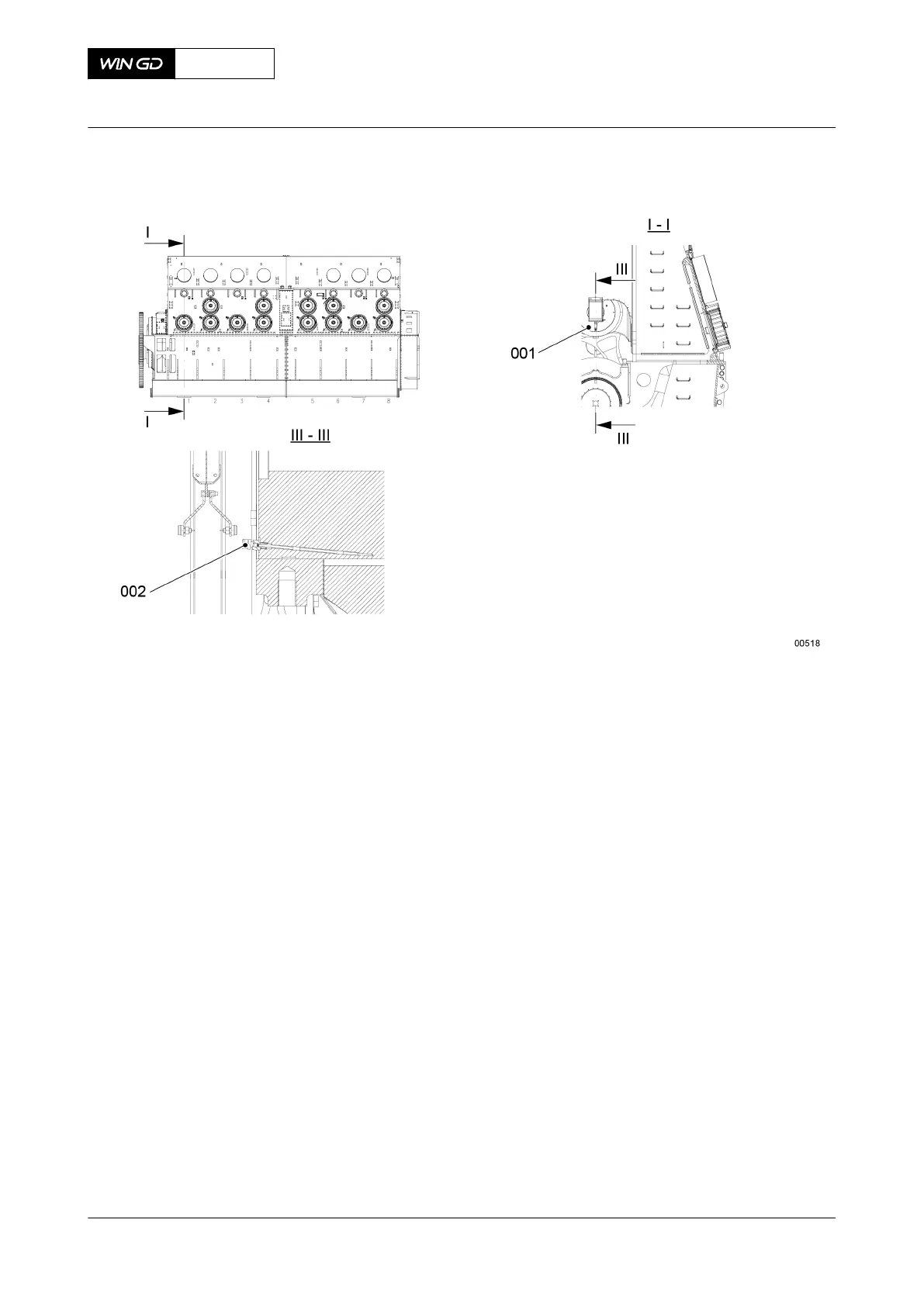
3 Attach the engine room crane to the lifting tool (001, Figure 8-49).
4 Operate the engine room crane to lower the lifting tool (001) on to the crosshead pin.
5 Remove the engine room crane.
6 Attach the lifting tool (001) to the crosshead pin with the four round nuts.
7 Put oil on the threads and surfaces that will touch on the screws (005) on the lifting tools
(002).
8 Attach a lifting tool (002) to each side of the connecting rod with the screws (005).
9 Torque the screws (005) to the correct value, refer to section 16.1 Tightening
instructions.
10 Put the platform (011) on the crosshead pin.
11 Put the tools that follow on the platform (011):
•
Spur-geared chain block (006)
•
Spur-geared chain block (012)
•
Spur-geared chain block (007)
•
Eye bolts (010)
•
Shackles (009)
•
Shackles (013)
•
Bracket (008).
NOTE: Make sure that the tools do not fall into the machine room.
X72DF
AA00-3326-00AAA-520A-A
Maintenance Manual Crosshead - remove
Winterthur Gas & Diesel Ltd.
- 447 - Issue 002 2020-10