PROCEDURE
1 Start the engine in the direction AHEAD to move the crankshaft (002, Figure 6-17) fully
forward. The crankshaft must touch the thrust pads.
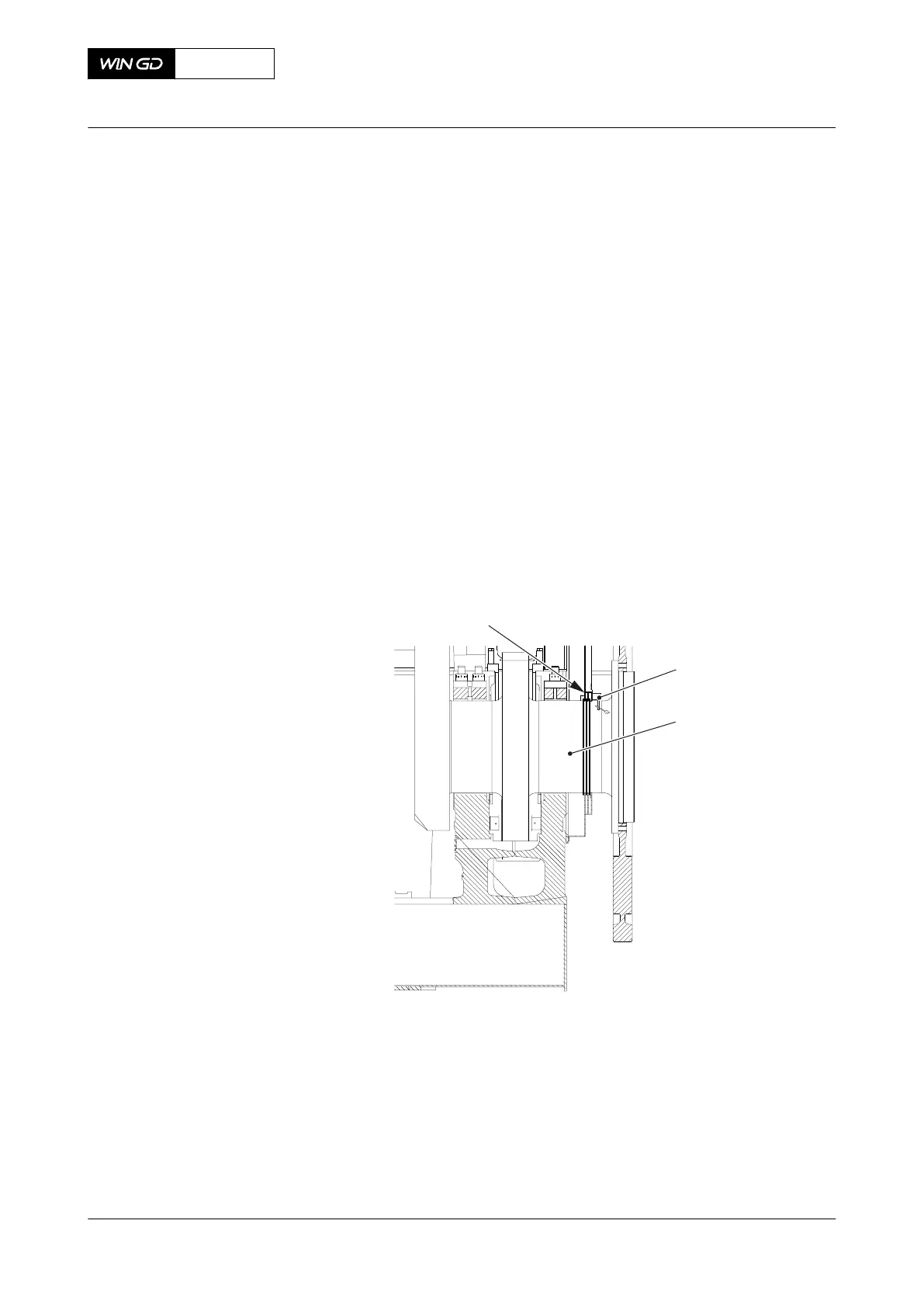
2 Stop the engine.
3 Put the dial gauge (001) in position on the oil baffle (003) and record the value.
4 Remove the dial gauge (001).
5 Start the engine in the direction REVERSE to move the crankshaft fully rearward. The
crankshaft must touch the thrust pads.
6 Stop the engine.
7 Put the dial gauge (001) in position on the oil baffle (003) and record the value.
8 Remove the dial gauge (001).
9 Compare all recorded values with those given in the engine documents on the Check
Dimensions page. Refer also to the applicable data in section 3.3 Clearances - general.
NOTE: If the measured values are more than the nominal values given, the thrust
pads are worn. If necessary replace the thrust pads.
Fig 6-17 Axial clearance
CLOSE UP
• None
X72DF
AA00-1203-00AAA-360A-A
Maintenance Manual Thrust bearing - do a check of the axial clearance with a dial
gauge
Winterthur Gas & Diesel Ltd.
- 135 - Issue 002 2020-10