Fig 8-32 Top bearing shell - move
005
001
002
003
003
004
004
006
009
004
008
010
011
002
005
007
008
00768
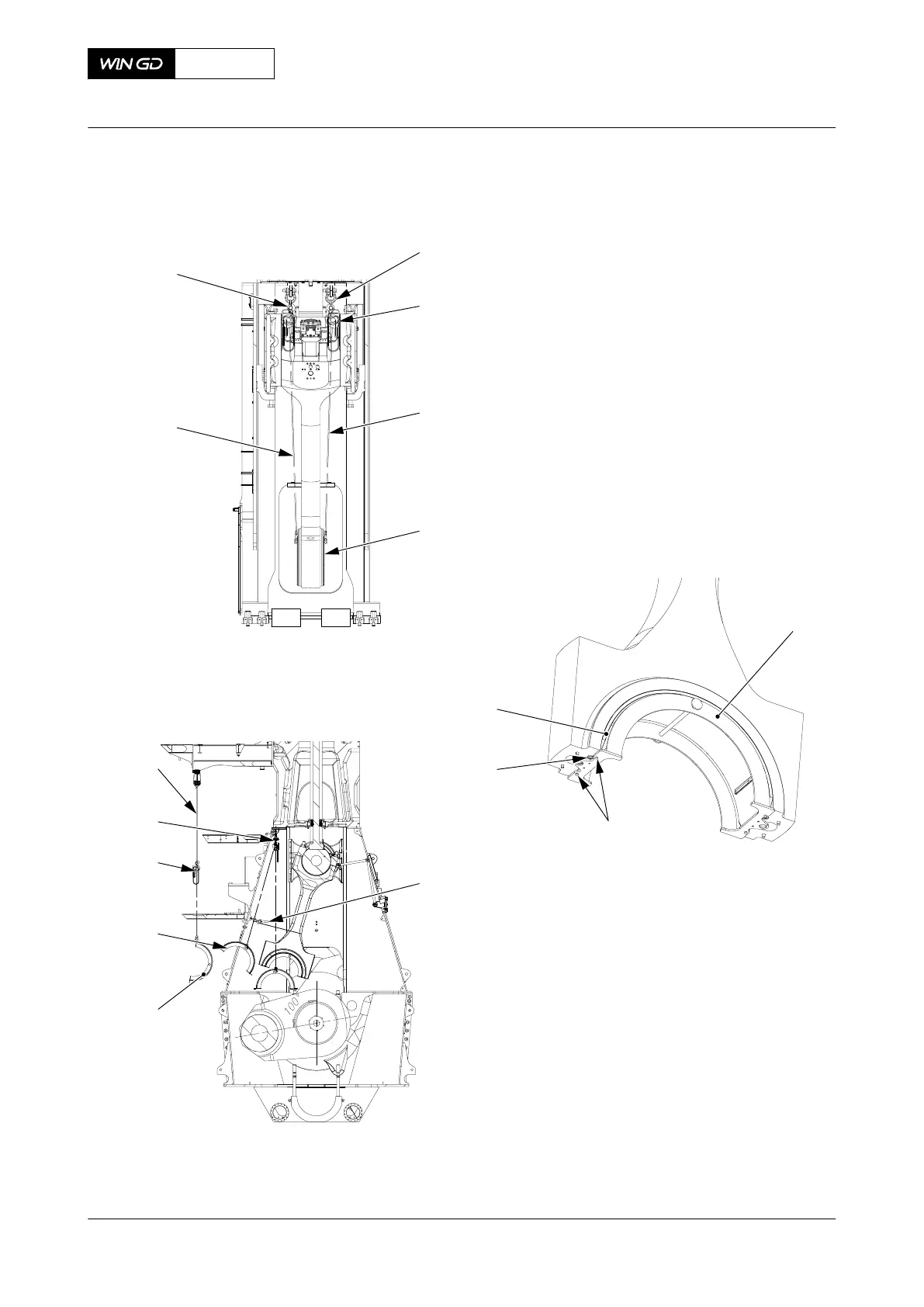
14 Operate the turning gear to move the crank (002, Figure 8-33) to the position shown.
15 Make sure that there is no load on the points (X) between the connecting rod (003) and
the crank pin (002).
X72DF
AA00-3303-03AAA-720A-A
Maintenance Manual Connecting rod - install the bottom end bearing
Winterthur Gas & Diesel Ltd.
- 413 - Issue 002 2020-10
 Loading...


