PROCEDURE
1 Remove all the protection from the sealing faces in the top housing (001, Figure 13-6)
and the exhaust valve control unit (VCU) (002).
2 Put oil on the new O-rings (009) and O-rings (010).
3 Attach the O-rings to the hydraulic pipe (004).
4 Make sure that the claws (007, 012) are correctly attached to the hydraulic pipe (004).
NOTE: You can adjust the claws with an open-ended wrench.
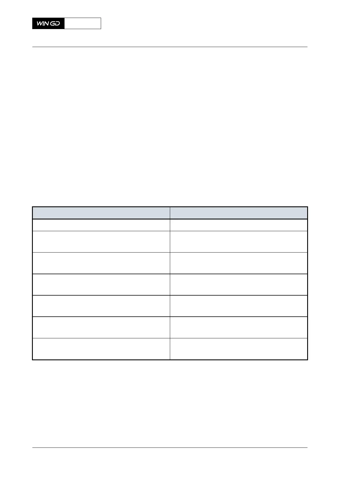
5 Make sure that the distance X between the ends of the hydraulic pipe (004) and the
claws (007, 012) refers to Table 13-2 - Distance X for hydraulic pipe exhaust valve.
6 Apply oil to the threads of all the screws (008, 010).
7 Carefully put the hydraulic pipe (004) in position in the top housing (001) and the VCU
(002).
8 Torque symmetrically the screws (008) to the correct value, refer to section 16.1
Tightening instructions.
9 Torque symmetrically the screws (010) to the correct value, refer to section 16.1
Tightening instructions.
Tab 13-2 Distance X for hydraulic pipe exhaust valve
Engine type Distance X [mm]
X35, X35-B 5.0
X40, X40-B
X40DF
5.0
X52
X52DF
5.5
X62, X62-B
X62DF
5.5
X72, X72-B
X72DF
5.5
X82, X82-B
X82DF
6.0
X92, X92-B
X92DF
9.5
X72DF
AA00-8460-00AAA-720A-A
Maintenance Manual Hydraulic pipe exhaust valve - install
Winterthur Gas & Diesel Ltd.
- 741 - Issue 002 2020-10