PROCEDURE
1 Read the data in 3.1 Lifting tools.
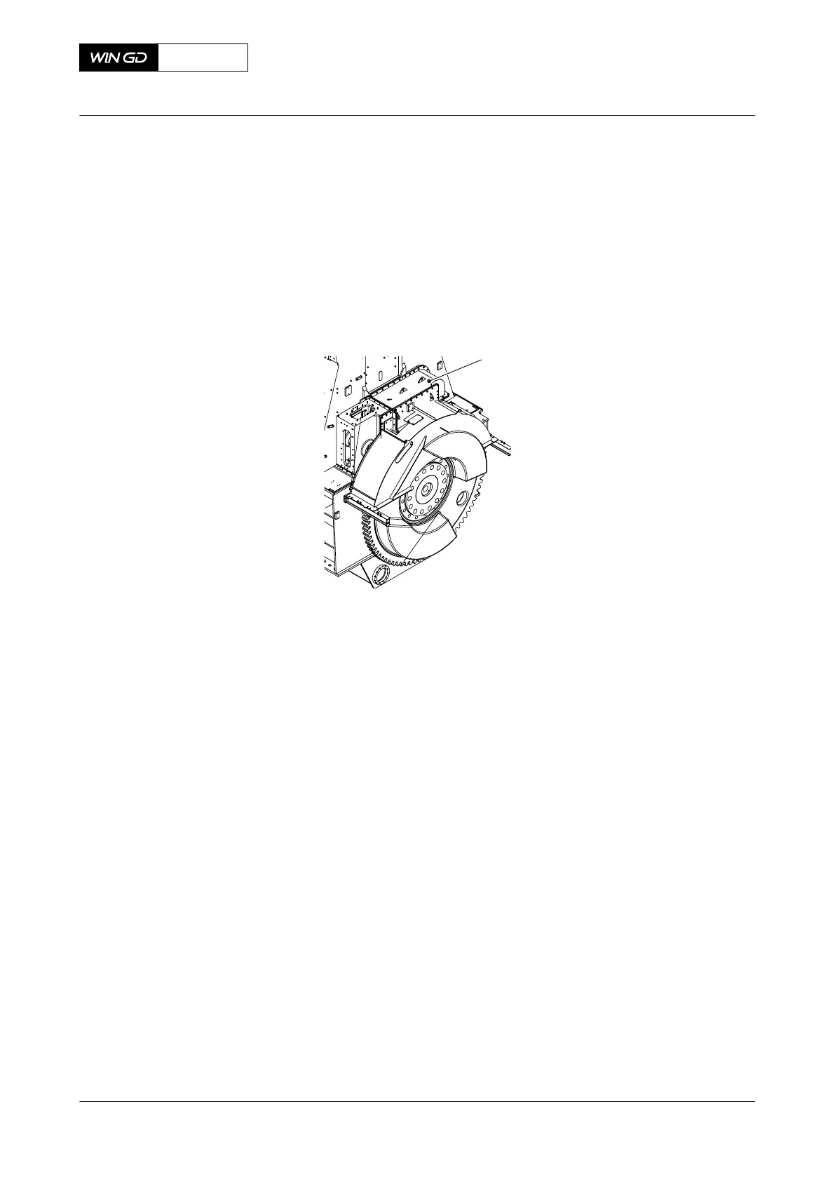
2 Remove the cover (001, Figure 6-19).
Fig 6-19 Cover - remove
3 Record the positions of the thrust bearing pads.
4 Remove the three bolts (001, Figure 6-20) from each of the four arbor supports (002).
5 Remove and discard the locking plates (003).
6 Attach the eye bolt (004) to the arbor support.
7 Attach the two shackles (013) to the gallery.
8 Attach the spur-geared chain block (005) to the shackle (013) and the M12 eye bolt
(009).
9 Use the chain block (005) to remove the four arbor supports (002).
10 Attach the manual ratchet (010) to the other shackle (009).
11 Attach the link (012) to the manual ratchet (010) and the chain block (005).
12 Attach the other manual ratchet (011) to the link (012).
13 Remove the temperature sensors from the thrust pad.
14 Attach the carrier (008) to the gear wheel.
15 Attach the eye bolt (006) to the top thrust pad (007).
X72DF
AA00-1203-00AAA-520A-A
Maintenance Manual Thrust bearing - remove the pads
Winterthur Gas & Diesel Ltd.
- 141 - Issue 002 2020-10