PROCEDURE
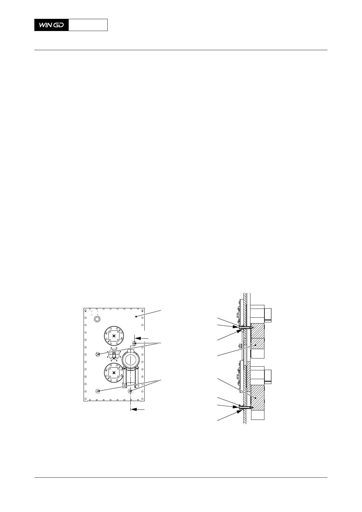
1 Lock the top and bottom counterweights as follows:
1.1 Apply lubricating oil to the thread and bottom of the head of the clamping screw
(004, Figure 12-7) and the nut (006).
1.2 Remove the two screws (002) from the main cover (001).
1.3 Put the two clamping screws (004) and the nuts (006) in position on the top
counterweight (007).
1.4 Torque the two clamping screws (004) to 60 Nm.
1.5 Torque the nut (006) to 60 Nm.
1.6 Put the M12 bolt (005) in position through the clamping screw (004).
1.7 Torque the M12 bolt (005) to 60 Nm.
1.8 Apply oil to the thread and bottom of the head of the clamping screw (009) and
the nut (011).
1.9 Remove the two screws (003) from the cover (001).
1.10 Put the two clamping screws (009) and the nuts (011) in position on the bottom
counterweight (008).
1.11 Torque the clamping screw (009) to 60 Nm.
1.12 Torque the nut (009) to 60 Nm.
1.13 Put the M12 bolt (010) in position through the clamping screw (009).
1.14 Torque the M12 bolt (010) to 60 Nm.
Fig 12-7 Counterweights - lock
00577
001
004
002
003
I
I
005
006
007
009
010
011
008
2 Remove the bearings as follows:
X72DF
AA00-7758-00AAA-520A-A
Maintenance Manual Integrated electric balancer - remove the bearing (engine side)
Winterthur Gas & Diesel Ltd.
- 691 - Issue 002 2020-10