PROCEDURE
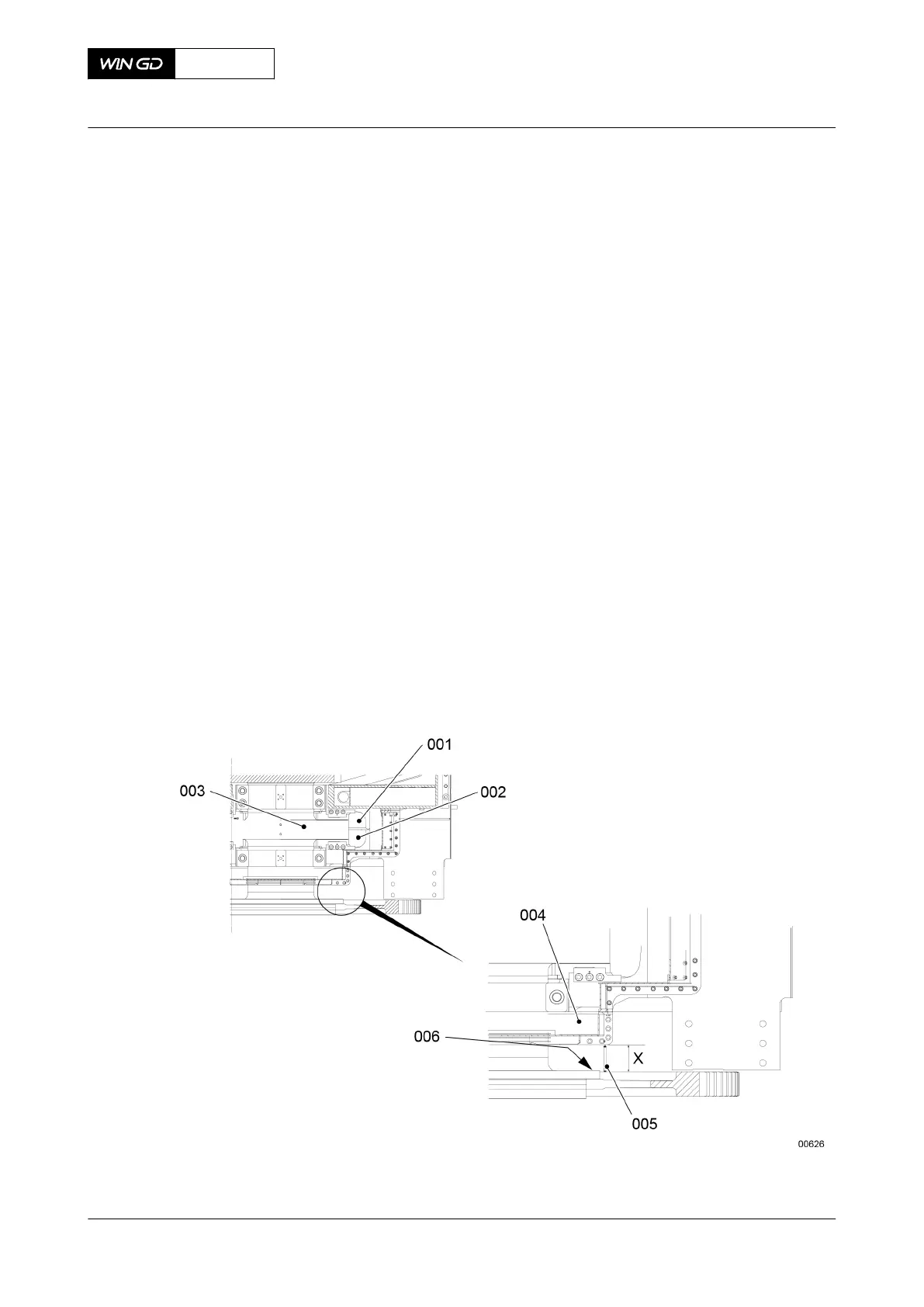
1 Start the engine in the direction AHEAD to move the crankshaft fully forward. The
crankshaft (003, Figure 6-18) must touch the thrust pads (002).
2 Stop the engine.
3 Make sure that the crankshaft (003) does not move.
4 Use the micrometer 94101 (005) to measure the distance between the crankshaft flange
(006) and the oil baffle (004).
5 Record the value.
6 Remove the micrometer (005).
7 Start the engine in the direction ASTERN to move the crankshaft fully rearward. The
crankshaft (003) must touch the thrust pads (001).
8 Stop the engine.
9 Make sure that the crankshaft does not move.
10 Use the micrometer (005) to measure the distance between the crankshaft flange (006)
and the oil baffle (004).
11 Record the value.
12 Remove the micrometer (005).
13 Compare all recorded values with those given in the engine documents on the Check
Dimensions page. Refer also to the applicable data in section 3.3 Clearances - general.
NOTE: If the measured values are more than the nominal values given, the thrust
pads are worn. If necessary replace the thrust pads.
Fig 6-18 Axial clearance - micrometer
X72DF
AA00-1203-00AAA-360B-A
Maintenance Manual Thrust bearing - do a check of the axial clearance with a inside
micrometer
Winterthur Gas & Diesel Ltd.
- 137 - Issue 002 2020-10