PROCEDURE
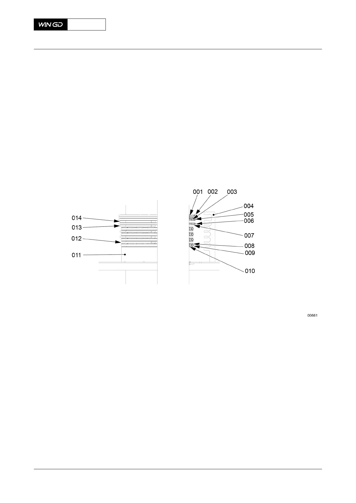
1 Attach the two parts of the clamp ring 94231A (011, Figure 7-30) to the piston rod.
2 Put the three parts of the ring support (010) and the scraper ring 3-part (008) on the
clamp ring (011).
3 Use the assembly tool to attach the spring (009) to the ring support (010).
4 Put the two parts of the distance piece (012) on the ring support (010).
Fig 7-30 Piston rod gland - assemble
5 Put the next three parts of the ring support (010) and the scraper rings (008) on the
distance piece. Make sure that there is an equal distance between the three parts.
6 Use the assembly tool to attach the tension spring (009) to the ring support (010).
7 Remove the distance piece (012).
8 Do Step 4 to Step 7 again until the four ring supports (010) are attached to the piston
rod.
9 Put the two parts of the distance piece (013) on the top ring support (010).
10 Put the gasket 4-part and the gasket 4-part (007) on the distance piece (013).
11 Use the assembly tool to attach the spring (006).
12 Remove the distance piece (013).
13 Put the two parts of the distance piece 94231B (014) on the gasket 4-part (007).
14 Put the gasket 4-part (003) on the distance piece 94231B. Make sure that there is an
equal distance between the four parts.
15 Put the scraper ring 4-part (with dowel pin) (002) on the gasket 4-part (003). Make sure
that there is an equal distance between the four parts. Make sure that the spring dowel
pin (not shown) is correctly installed.
16 Use the assembly tool 94233 to attach the spring (005).
X72DF
AA00-2303-00AAA-720A-A
Maintenance Manual Piston rod gland - install
Winterthur Gas & Diesel Ltd.
- 232 - Issue 002 2020-10