PROCEDURE
1 Apply Molycote G-Rapid Plus to the disassembly / assembly tool (006, Figure 7-18).
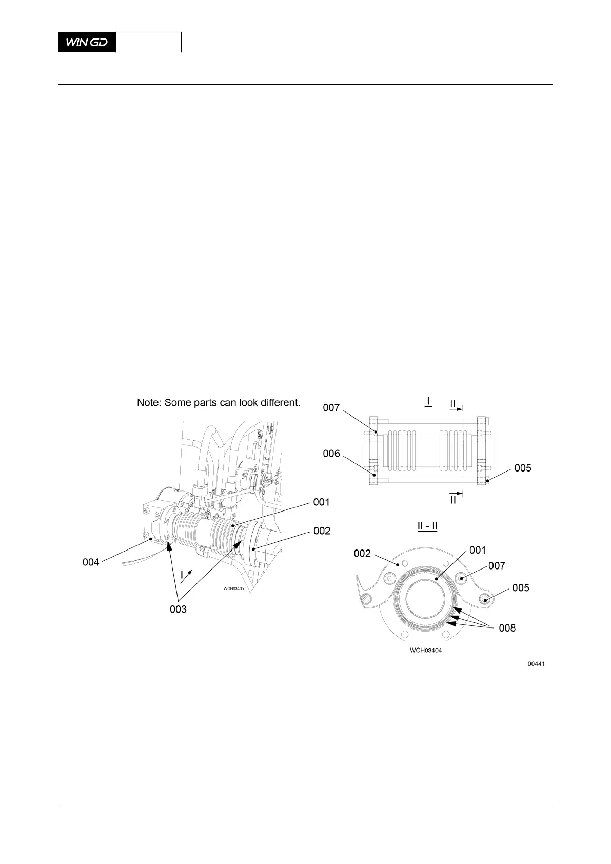
2 Remove the screws (003) on each side of the compensator (001).
3 Put the tool (006) in position on the compensator (001) as shown.
NOTE: The tool (006) is shorter than the installed length of the compensator (001).
4 Attach the tool (006) to the flanges of the compensator (001) with the four screws (007).
5 Tighten the four screws (007).
6 Tighten equally the two bolts (005) to compress the compensator (001).
7 Continue to tighten the bolts (005) until you can remove the compensator (001).
8 Carefully remove the tool (006) together with the compensator (001).
9 Make sure that the six O-rings (008) (on the flange couplings) are serviceable. If
necessary, replace the O-rings.
10 Remove the tool (006) from the compensator (001).
11 Put the compensator (001) in a clean, dry area.
Fig 7-18 Compensator - remove
12 Put an oil tray under the gas admission valve (GAV) (005, Figure 7-19).
13 Make sure that the power supply to the rail valve (010) is set to off.
14 Disconnect the electrical connections to the rail valve (010) and the valve stroke sensor
(007).
15 Loosen the four screws (002).
16 Remove the pipe.
NOTE: During this step, make sure that you do not damage the sealing face of the
pipe (001).
X72DF
AA00-2140-00AAA-520A-A
Maintenance Manual Gas admission valve - remove
Winterthur Gas & Diesel Ltd.
- 207 - Issue 002 2020-10