PROCEDURE
1 Operate the turning gear to move the roller of the related fuel pump to its highest
position (TDC).
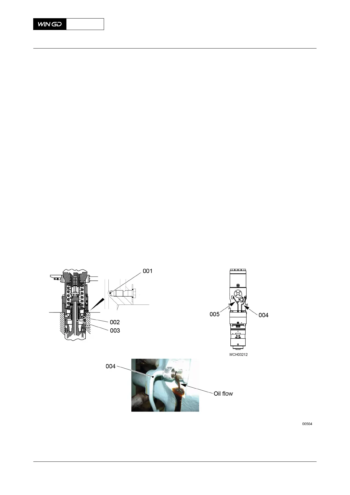
NOTE: The oil flows through the throttle (001, Figure 10-19) to the bottom housing
(002) and the guide piston (003).
2 Remove the oil drain pipe (004) from the fuel pump.
3 Set to ON the servo oil service pump.
4 After one minute, make sure that you can see the oil flow as shown.
5 If the oil does not flow as shown, read the data in Technical Bulletin RT-180.
6 Make sure that the oil flows in the inlet pipe (005).
NOTE: If the oil in the inlet pipe (005) does not flow freely, it is possible that there are
unwanted particles in the oil supply system. If you find particles, remove them.
7 If there is incorrect oil flow, or no flow through the drain bore do Step 7.1 to Step 7.4:
7.1 If the oil cannot flow freely, flush the bores with WD-40.
7.2 If there is no oil flow, use a heat gun to apply heat to the clogged drain bore.
7.3 Use a small drill bit to open the bore.
7.4 Remove the particles with a nylon brush.
8 Install all unions and plugs.
9 Connect the oil drain pipe (004) to the fuel pump.
Fig 10-19 Fuel pump - oil flow
X72DF
AA00-5556-00AAA-320A-A
Maintenance Manual Fuel pump - do a test of the operation
Winterthur Gas & Diesel Ltd.
- 573 - Issue 002 2020-10