10/00
4-117
Phaser 790/DocuColor 2006
REP 10.6, REP 10.7
Repairs and Adjustments
Initial Issue
REP 10.6 Pressure Roll Heat Lamp
Parts List on PL 8.3
Removal
WARNING
To avoid personal injury or shock, do not perform repair activities with the power switch
on or electrical power applied to the machine.
1. Switch off the machine power and disconnect the machine Power Cord.
2. Remove the Main Fuser Assembly (REP 10.2).
3. Remove the Upper Guide Assembly (REP 10.3).
4. Remove the Upper Plate (REP 10.4).
CAUTION
Be careful not to touch the surface of the Pressure Roll Heat Lamp while removing the lamp.
Contamination from hands can damage the lamp.
The connector for the Pressure Roll Heat Lamp is tightly connected. Be careful not to damage
the lamp when disconnecting the connector.
The gear is no longer secured when the Fuser Rear Cover is removed. Be careful not to allow
the gear to fall out while removing the cover.
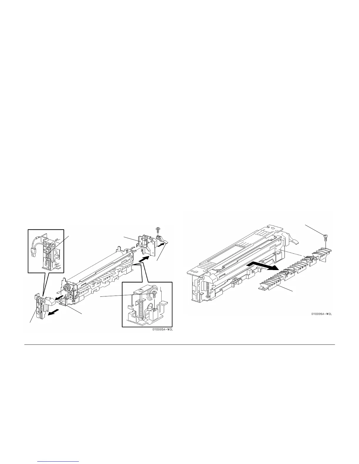
5. Remove the Pressure Roll Heat Lamp (Figure 1).
Replacement
1. Reinstall the Pressure Roll Heat Lamp in the reverse order of removal.
2. Check the Fuser Nip (ADJ 10.1).
Figure 1 Removing the Pressure Roll Heat Lamp
REP 10.7 Lower Guide Assembly
Parts List on PL 8.2
Removal
WARNING
To avoid personal injury or shock, do not perform repair activities with the power switch
on or electrical power applied to the machine.
1. Switch off the machine power and disconnect the machine Power Cord.
2. Remove the Main Fuser Assembly (REP 10.2).
3. Remove the Upper Guide Assembly (REP 10.3).
CAUTION
Be careful not to damage the surface of the Pressure Roll while removing the Lower Guide
Assembly.
4. Remove the Lower Guide Assembly (Figure 1).
Replacement
CAUTION
Do not damage the Fuser Exit Actuators and ensure that the actuators do not interfere with the
Fuser Exit Sensors and fall out while installing the Lower Guide Assembly.
1. Reinstall the Lower Guide Assembly in the reverse order of removal.
Figure 1 Removing the Lower Guide Assembly
1
Remove the
screw then
remove the
handle
2
Remove the Fuser
Front Cover
3
Free the harness
and disconnect
the connector
4
Remove the Fuser Rear Cover
6
Remove the Pres-
sure Roll Heat Lamp
from the rear
5
Remove the
screw
1
Remove the
screw
2
Remove the
Lower Guide
Assembly
 Loading...