27 - 4
27.1 Direct Connection To CPU
27.1.2 Connection Cable
27.1.2 Connection Cable
The RS-232 cable used for connecting the GOT to the PLC should be prepared by the user.
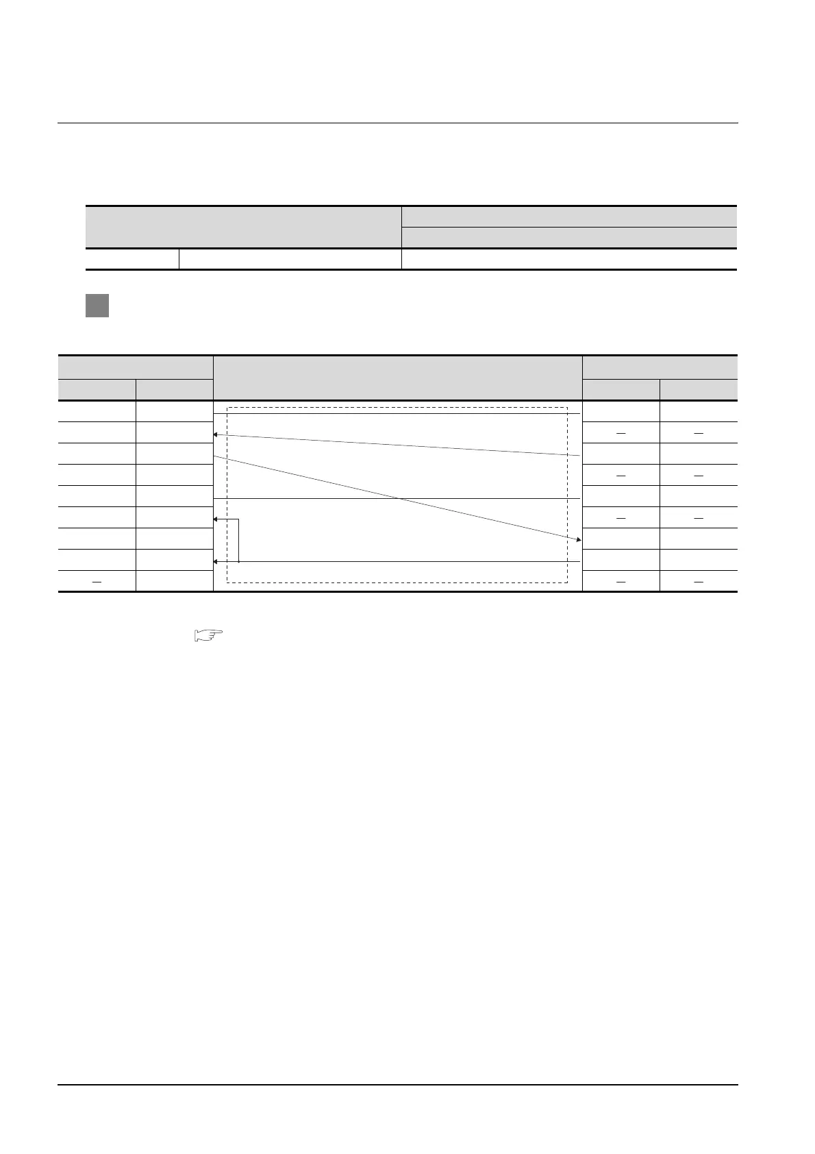
The following provides connection diagrams for each cable, connector specifications and other information.
1 Connection diagram
(1) RS-232 cable 1)
*1 For details of the CNC side connection, refer to the following manual.
MELDAS C6/C64 CONNECTION AND MAINTENANCE MANUAL BNP-B2255
MELDAS C6/C64 NETWORK MANUAL BNP-B2372
Model name
Connection cable
RS-232 cable
CNC MELDAS C6/C64 RS-232 cable
GOT side
Cable connection and signal direction
CNC
*1
Signal name Pin No. Pin No. Signal name
CD 1 1GND
RD(RXD) 2
SD(TXD) 3 6SD
ER(DTR) 4
SG 5 11 GND
DR(DSR) 6
RS(RTS) 7 16 RD
CS(CTS) 8 18 ER(DTR)
9

 Loading...


