19.5 Message Formats
19.5.4 Formats 3 to 6 (A compatible 1C frame)
19 - 41
17
CONNECTION TO
ALLEN-BRADLEY PLC
18
CONNECTION TO
SIEMENS PLC
19
MICROCOMPUTER
CONNECTION
20
CONNECTION TO OMRON
TEMPERATURE
CONTROLLER
21
CONNECTION TO
YAMATAKE TEMPERATURE
CONTROLLER
22
CONNECTION TO RKC
TEMPERATURE
CONTROLLER
23
CONNECTION TO
FREQROL SERIES
INVERTER
24
SERVO AMPLIFIER
CONNECTION
19.5.4 Formats 3 to 6 (A compatible 1C frame)
1 Basic format of data communication
This is the same message format as when communication is performed using the dedicated protocol (A
compatible 1C frame) of the A Series computer link module.
For details of the basic format of data communication, refer to the following manual:
Q Corresponding MELSEC Communication Protocol Reference Manual
This section describes items whose settings differ from the dedicated protocol of the A Series computer
link modules, and the dedicated commands for a GOT microcomputer connection.
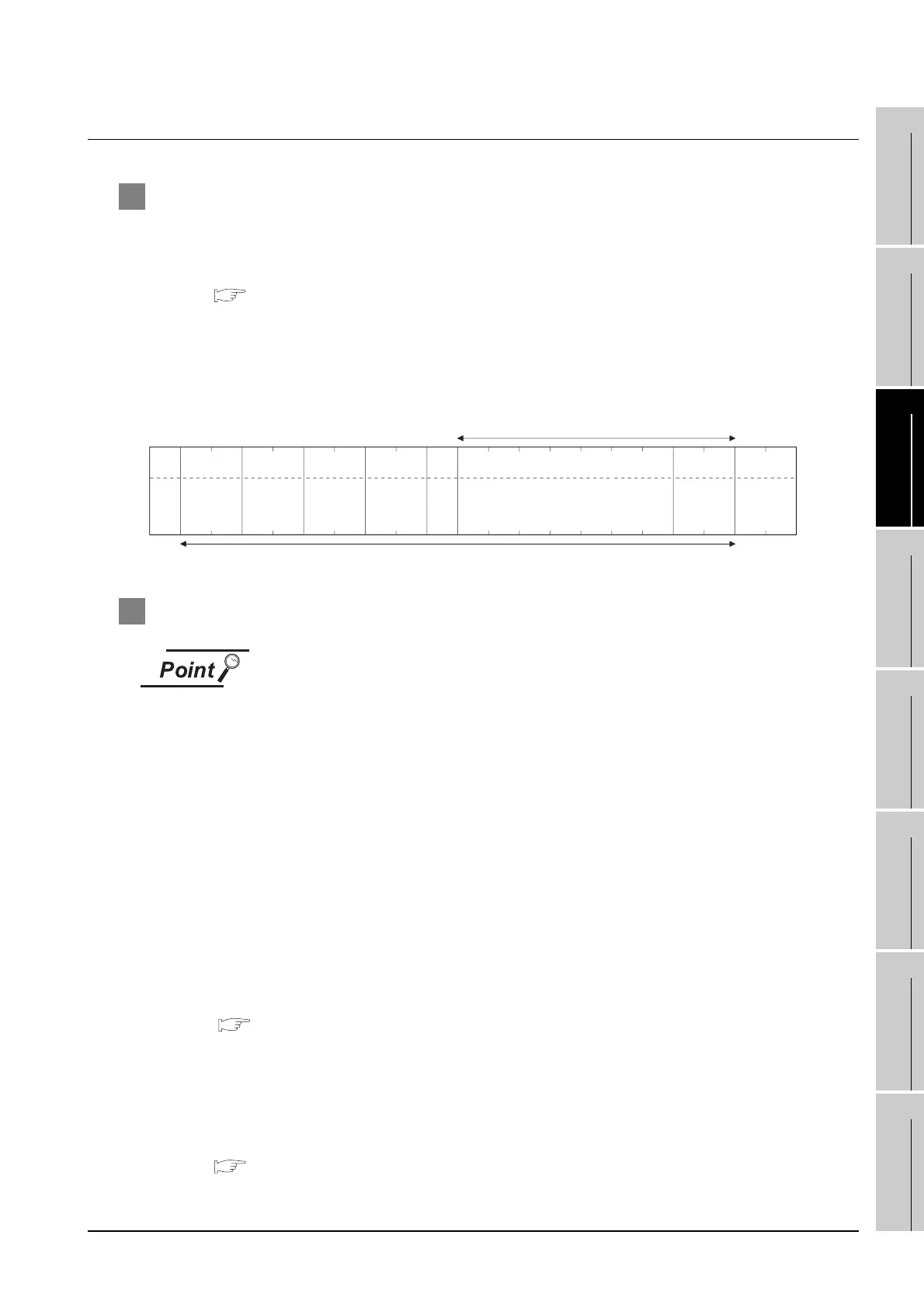
Example: Request message for the batch read in word units (QR) command in format 4 (A compatible
1C frame (format 2))
2 Details of data items in message format
Data code during communication
Communication is performed in ASCII code.
(1) Block No, PLC No.
The block No. and PLC No. are ignored in a microcomputer connection of the GOT.
Specify "00".
"00" is converted to a 2-digit ASCII code (Hex) and transmitted from the upper digit.
(2) Station No.
Station No. is used to identify the GOT with which the host communicates. (Setting range: 0 to 31)
The data notated in decimal is converted to a 2-digit ASCII code (Hex) and transmitted from the
upper digit.
The GOT processes the command whose station No. matches to "Host Address (0 to 31)" set at
"Communication Detail Settings". (The message of command whose station No. does not match is
ignored.)
For setting method of "Communication Detail Settings", refer to the following.
Section 19.6.3 Setting communication interface (Communication settings)
(3) Command
Specifies the contents of the GOT to which the host accesses.
The command is converted to a 2-digit ASCII code (Hex) and transmitted from the upper digit.
For details of the commands that can be used, refer to the following.
Section 19.5.2 List of commands
Sum check is performed in this range.
05
H
ENQ
(H) (L)
BA
42
H 41H
Sum
Check
(H) (L)
Command
R
52
H
Q
51
H
(H)
Address
D1
44
H 31H
––
0
30
H
0
30
H
(H) (L)
Number
of points
02
30
H
32
H
(H) (L)
Block No.
0
30
H
0
30
H
(H) (L)
Station
No.
0
30
H
0
30
H
(H) (L)
PLC No.
0
30
H
0
30
H 30H
Wait
0
–
0
30
H
(L)
0
30
H
0
30
H
––
Character A section

 Loading...


