5.3 PLC Side Setting
5.3.2 Connecting to MELSECNET/10 network module (QnA Series)
5 - 29
1
OVERVIEW
2
BUS CONNECTION
3
DIRECT CONNECTION
TO CPU
4
COMPUTER LINK
CONNECTION
5
MELSECNET/10
CONNECTION (PLC TO
PLC NETWORK)
6
CC-Link CONNECTION
(INTELLIGENT DEVICE
STATION)
7
CC-Link CONNECTION
(Via G4)
8
ETHERNET
CONNECTION
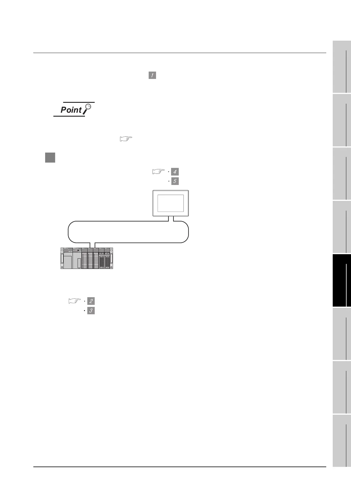
5.3.2 Connecting to MELSECNET/10 network module (QnA Series)
This section describes the settings of the GOT and MELSECNET/10 network module (QnA series) in the
case of system configuration shown as .
In this section, the network parameter (common parameter) of GX Developer is taken as an exmaple to pro-
vide explanations.
MELSECNET/10 network module (QnA Series)
For details of the MELSECNET/10 network module (QnA Series), refer to the
following manual.
For QnA/Q4AR MELSECET/10 Network Svstem Reference Manual
1 System configuration
*1 The MELSECNET/10 network module is mounted at slot 0 of the base unit.
The start I/O No. of the MELSECNET/10 network module is set at "0".
<MELSECNET/10 network module> *1 (Use the default value for settings other
than the following.)
Station No.
Mode
Network type
Network No.
Total stations
Network range assignment: B0000
H to B00FFH
W0000H to W00FFH
Switch setting of MELSECNET/10 network module
[Network parameter] of GX Developer
[Communication settings] of GT Designer2
5
Setting of the MELSECNET/10 communication unit
MELSECNET/10 (PLC to PLC network)
<GOT> (Use the default value for settings other
than the following.)
Station No.
Mode
Network No.
Network range assignment: B0100
H
to B01FF
H
: 2
: Online
: 1
: 1
: 1
: 2
: Online
: MNET/10 (Controlling station)
W0100
H to W01FFH

 Loading...


