6.2 Preparatory Procedures for Monitoring
6.2.5 Attaching communication unit and connecting cable
6 - 13
1
OVERVIEW
2
BUS CONNECTION
3
DIRECT CONNECTION
TO CPU
4
COMPUTER LINK
CONNECTION
5
MELSECNET/10
CONNECTION (PLC TO
PLC NETWORK)
6
CC-Link CONNECTION
(INTELLIGENT DEVICE
STATION)
7
CC-Link CONNECTION
(Via G4)
8
ETHERNET
CONNECTION
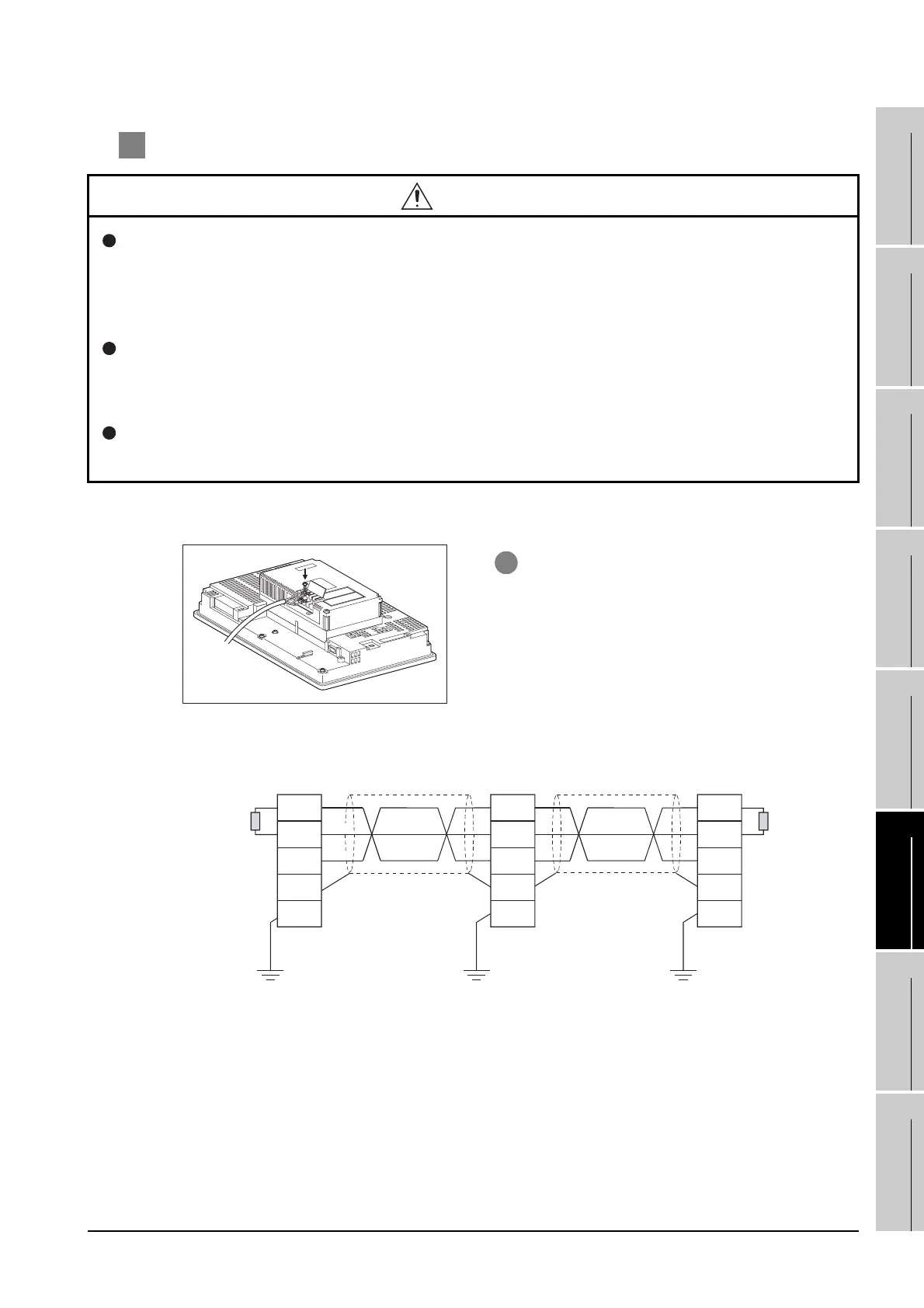
2 Connecting the cable
(1) CC-Link dedicated cable connection method
(2) Wiring diagram
CAUTION
Always ground the FG terminal of the GOT power supply and the FG1 terminal of this unit to the
protective ground conductor.
Be sure to ground the GOT and this unit separately.
Failure to do so may cause an electric shock or malfunctions.
Use applicable solderless terminals and tighten them with the specified torque.
If any solderless spade terminal is used, it may be disconnected when the terminal screw comes
loose, resulting in failure.
Be sure to tighten any unused terminal screws with a torque of 0.36 to 0.48N•m.
Failure to do so may cause a short circuit due to contact with a solderless terminal.
1 Connect the CC-Link cable to the terminal block
of the CC-Link communication unit.
If the CC-Link communication unit is terminal
station of the network, be sure to connect a
terminating resistor (packed together with the
CC-Link module) to the terminal block.
Terminating
resistor
Terminating
resistor
CC-Link module GOT
DA
DB
DG
SLD
FG
DA
DB
DG
FG1
SLD
DA
DB
DG
FG1
SLD
CC-Link dedicated cable CC-Link dedicated cable
(Blue)
GOT (Terminating station)
<Wiring diagram>
(White)
(Yellow)

 Loading...


