4 - 18
4.2 Connection Cable
4.2.1 RS-232 cable
4.2.1 RS-232 cable
The following shows the connection diagrams and connector specifications of the RS-232 cable used for
connecting the GOT to a PLC.
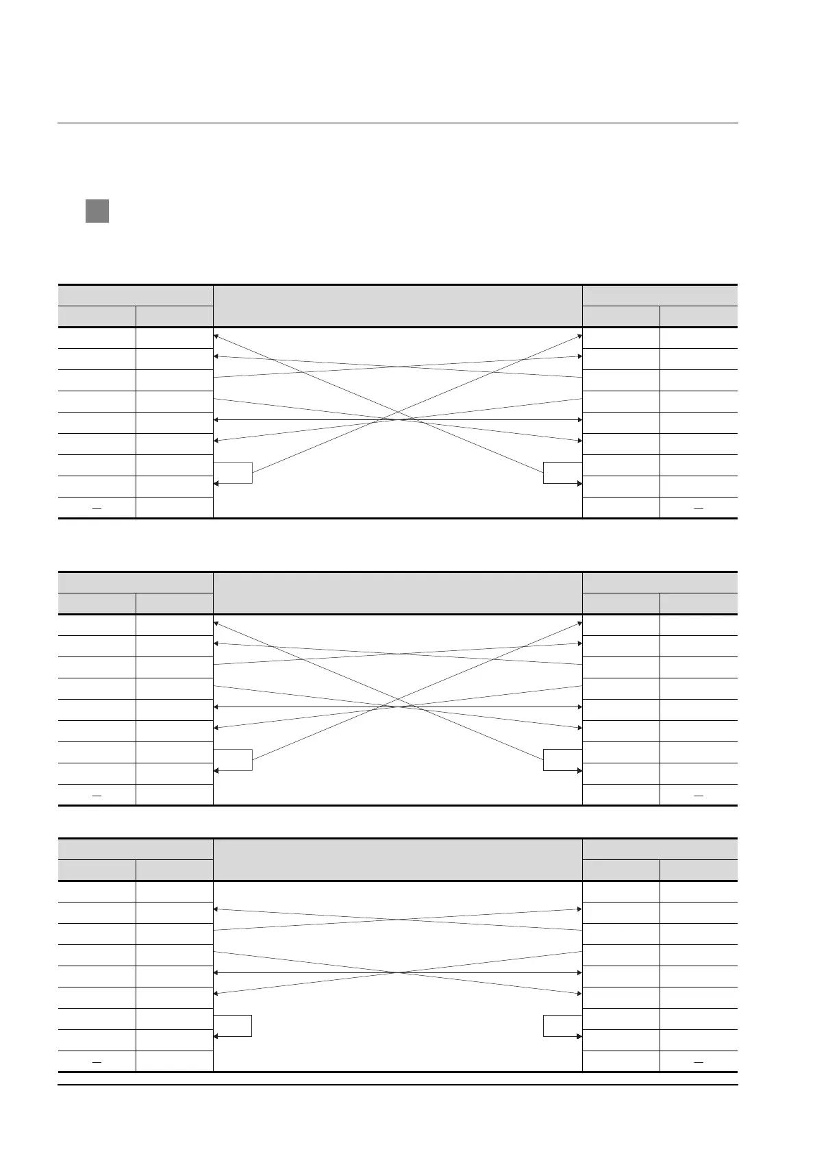
1 Connection diagram
(1) RS-232 cable 1) (when PLC CPU side connector is D-sub 9-pin)
(a) For the GT15
(b) For the GT11
<When connecting to the Q/Qn Serial Communication Module>
<When connecting to the Computer Link Module>
GOT side
Cable connection and signal direction
PLC side
Signal name Pin No. Pin No. Signal name
CD 1 1CD
RD(RXD) 2 2 RD(RXD)
SD(TXD) 3 3SD(TXD)
ER(DTR) 4 4ER(DTR)
SG 5 5SG
DR(DSR) 6 6 DR(DSR)
RS(RTS) 7 7 RS(RTS)
CS(CTS) 8 8CS(CTS)
9 9
GOT side
Cable connection and signal direction
PLC side
Signal name Pin No. Pin No. Signal name
CD 1 1CD
RD(RXD) 2 2 RD(RXD)
SD(TXD) 3 3SD(TXD)
ER(DTR) 4 4ER(DTR)
SG 5 5SG
DR(DSR) 6 6 DR(DSR)
RS(RTS) 7 7 RS(RTS)
CS(CTS) 8 8CS(CTS)
9 9
GOT side
Cable connection and signal direction
PLC side
Signal name Pin No. Pin No. Signal name
NC 1 1CD
RD(RXD) 2 2 RD(RXD)
SD(TXD) 3 3SD(TXD)
ER(DTR) 4 4ER(DTR)
SG 5 5SG
DR(DSR) 6 6 DR(DSR)
RS(RTS) 7 7 RS(RTS)
CS(CTS) 8 8CS(CTS)
9 9

 Loading...


