27.2 MELSECNET/10 Connection (PLC To PLC Network)
27.2.9 Checking for normal monitoring
27 - 37
25
BAR CODE READER
CONNECTION
26
PRINTER CONNECTION
27
CNC CONNECTION
28
MULTI-CHANNEL
FUNCTION
29
FA TRANSPARENT
FUNCTION
30
MULTIPLE-GT11
CONNECTION FUNCTION
31
GATEWAY FUNCTION INDEX
27.2.9 Checking for normal monitoring
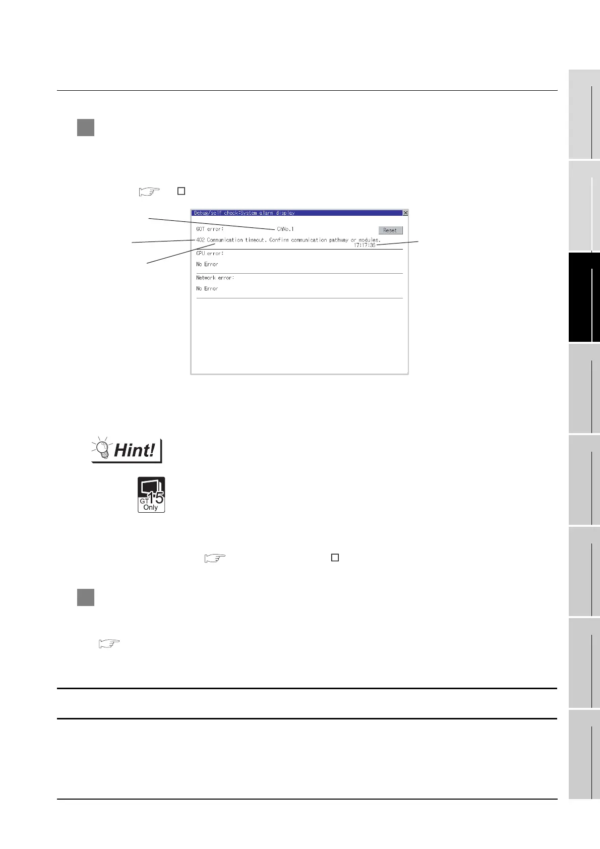
1 Check for errors occurring on the GOT.
Presetting the system alarm to project data allows you to identify errors occurred on the GOT, PLC
CPU, servo amplifier and communications.
For details on the system alarm, refer to the following manual.
GT User’s Manual (When using GT15)
Advanced alarm popup display
With the advanced alarm popup display function, alarms are displayed as a popup
display regardless of whether an alarm display object is placed on the screen or not
(regardless of the display screen).
Since comments can be flown from right to left, even a long comment can be
displayed all.
For details of the advanced popup display, refer to the following manual.
GT Designer2 Version Screen Design Manual
2 Confirming the CNC side setting
When connecting the GOT, setting is required for the CNC side.
Confirm if the CNC side setting is correct.
Section 27.2.10 CNC Side Settings
All settings related to communications are complete now.
Create screens on GT Designer2 and download the project data again.
Error code
Communication
Channel No.
Error message
Time of occurrence
(Displayed only for errors)

 Loading...


