28.2 System Configuration Examples
28 - 3
25
BAR CODE READER
CONNECTION
26
PRINTER CONNECTION
27
CNC CONNECTION
28
MULTI-CHANNEL
FUNCTION
29
FA TRANSPARENT
FUNCTION
30
MULTIPLE-GT11
CONNECTION FUNCTION
31
GATEWAY FUNCTION INDEX
28.2 System Configuration Examples
This manual uses the following system configuration as an example.
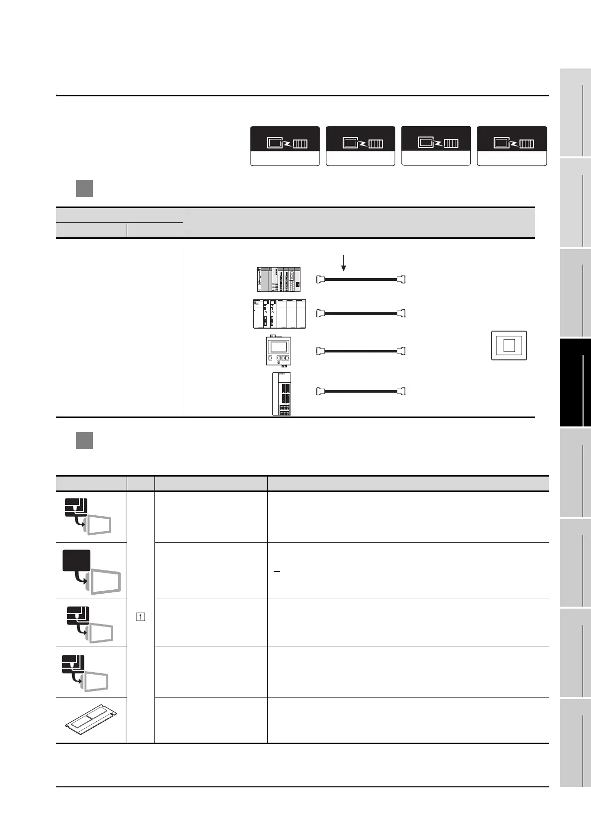
1 System configuration
2 System equipment
(1) GOT
(2) Cable
For selecting the cable, refer to each chapter indicating the system configuration.
Connection conditions
System configuration
Number of GOTs Distance
Differ according to connection type.
Image No. Name Model name
Bus connection unit
• For terminal GOT
GT15-QBUS
RS-232 interface
• For direct CPU connection
(Built into GOT)
RS-232 Communication unit
• For temperature controller
connection
GT15-RS2-9P
RS-422/485 Communication
unit
• For servo amplifier
connection
GT15-RS4-9S
Option function board
• For optional function
GT15-QFNB, GT15-QFNB16M, GT15-QFNB32M, GT15-QFNB48M
Bus(Q)
Communication driver
OMRON SYSMAC
Communication driver
OMRON THERMAC
/INPANEL NEO
Communication driver
MELSERVO-J3,
J2S/M
Communication driver
1
(Channel No.1)
(Channel No.2)
(Channel No.3)
(Channel No.4)
QCPU
MELSERVO-J2-Super
series
Cable selected according to connection type.
OMRON PLC
OMRON
temperature
controller
Bus connection
Direct CPU connection
Temperature controller
connection
Servo amplifier connection
Terminal
RS-232
RS-232
RS-422/48

 Loading...


