7.2 Preparatory Procedures for Monitoring
7.2.5 Attaching communication unit and connecting cable
7 - 11
1
OVERVIEW
2
BUS CONNECTION
3
DIRECT CONNECTION
TO CPU
4
COMPUTER LINK
CONNECTION
5
MELSECNET/10
CONNECTION (PLC TO
PLC NETWORK)
6
CC-Link CONNECTION
(INTELLIGENT DEVICE
STATION)
7
CC-Link CONNECTION
(Via G4)
8
ETHERNET
CONNECTION
7.2.5 Attaching communication unit and connecting cable
Cautions when attaching the communication unit and connecting the cable
Shut off all phases of the GOT power supply before attaching the communication
unit and connecting the cable.
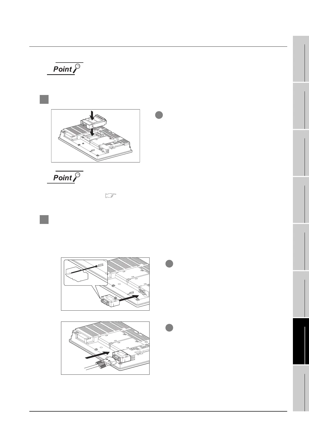
1 Attaching the communication unit
Serial communication unit
For details on the serial communication unit, refer to the following manual:
GT15 Serial Communication Unit User's Manual
GT15-RS2, GT15-RS4,GT15-RS4-TE
2 How to connect the cable
(1) How to connect the RS-422 cable
(a) For the GT15
• connection to the RS-232 interface
1 Attach the serial communication unit to the
extension unit connector on the GOT.
1 Connect the RS-422 conversion unit to the RS-
232 interface on the GOT.
2 Connect the RS-422 cable to the RS-422
conversion unit.

 Loading...


