8 - 30
8.3 PLC Side Setting
8.3.3 Connecting to Ethernet module (A Series)
8.3.3 Connecting to Ethernet module (A Series)
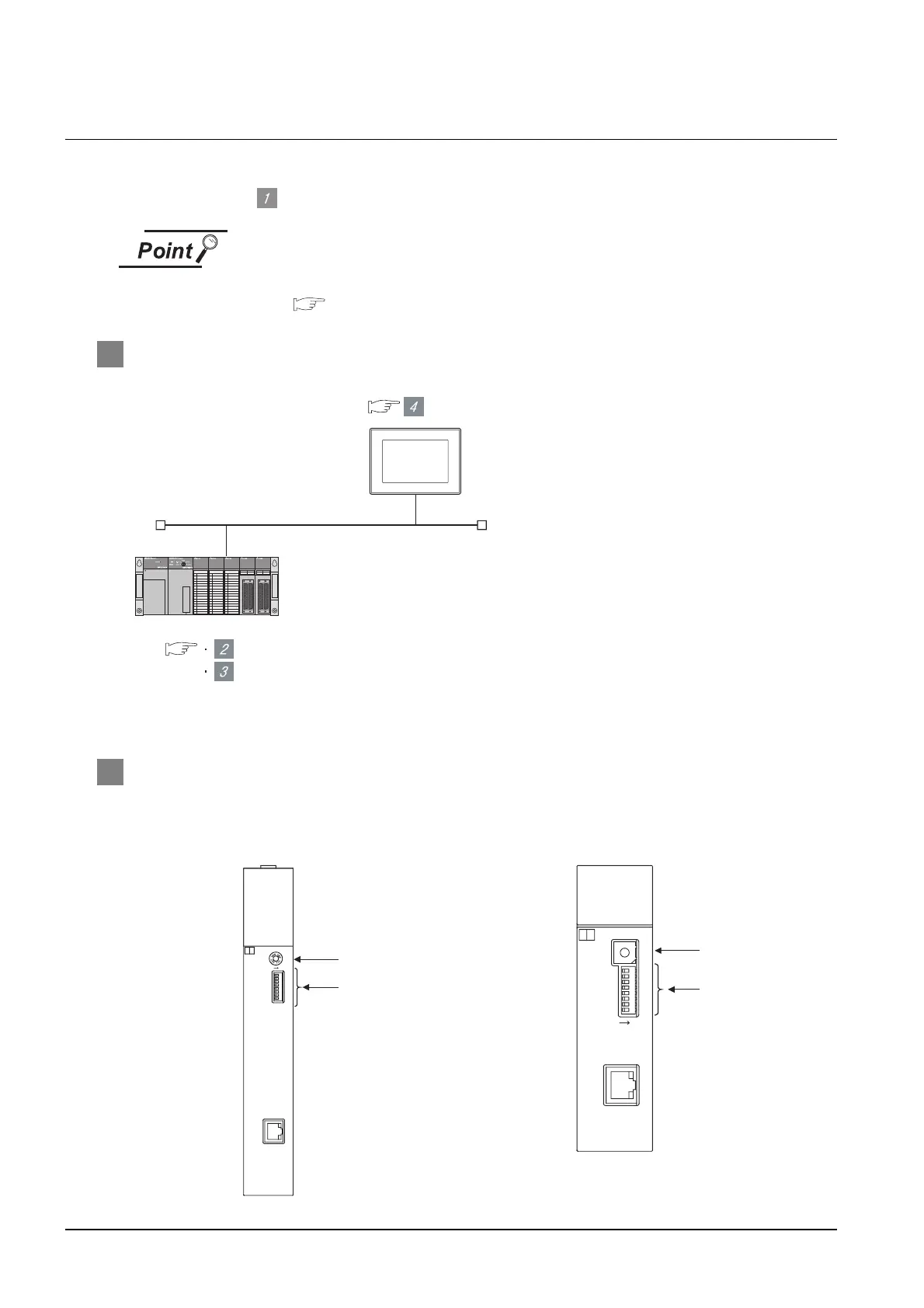
This section describes the settings of the GOT and Ethernet module (A Series) given for the system
configuration shown at .
Ethernet module (A Series)
For details of the Ethernet module (A Series), refer to the following manual.
For A Ethernet Interface Module User's Manual
1 System configuration
*1 The Ethernet module is mounted on the base unit slot 0.
The Start I/O No. of the Ethernet module is set to "0".
2 Switch settings of Ethernet module
Set the operation mode setting switch and exchange condition setting switch.
*2 The figure of AJ71E71N3-T and A1SJ71E71N3-T.
Switch setting of Ethernet module
Sequence program
<GOT> (The settings other than the
following are set to the default)
*1
Network No.
PC No.
IP address
Port No.
Communication format
: 1
: 1
: 192.168.0.18
: 5001
: UDP (fixed)
Network No.
PC No.
IP address
Port No.
Communication format
: 1
: 2
: 192.168.0.19
: 5001
: UDP(fixed)
<Ethernet module> (The settings other than the following are
set to the default)
[Communication settings] and [Ethernet setting] of GT
Designer2
A1SJ71E71N3-T
SW8
SW7
SW6
SW5
SW4
SW3
SW2
SW1
ON
10BASE-T
MODE
0:ONLINE
1:OFFLINE
2:TEST1
3:TEST2
4:TEST3
4
3
2
1
F
E
D
C
B
A
9
8
7
6
5
1SJ71E71N3-T
BSY
SW.ERR.
COM.ERR.
CPU R/W
TEST ERR.
TEST
A
RDY
RUN BUF1
BUF2
BUF3
BUF4
BUF5
BUF6
BUF7
BUF8
0
10BASE-T
4
C
8
J71E71N3-T
RUN BUF1
BUF2
BUF3
BUF4
BUF5
BUF6
BUF7
BUF8
RDY
BSY
SW.ERR.
COM.ERR.
CPU R/W
TEST
TEST ERR.
A
ON
0:ONLINE
4:TEST3
3:TEST2
2:TEST1
1:OFFLIN E
MODE
SW8
SW7
SW6
SW5
SW4
SW3
SW2
SW1
0
(1)
(2)
A1SJ71E71N3-T, A1SJ71E71N-B5, A1SJ71E71N-B2,
A1SJ71E71N-T, A1SJ71E71N-B5T,
A1SJ71E71-B5-S3, A1SJ71E71-B2-S3
J71E71N3-T, AJ71E71N-B5, AJ71E71N-B2,
J71E71N-T, AJ71E71N-B5T,
J71E71-S3
(1)
(2)
*2
*2

 Loading...


